PIC18C801-I/L Microchip Technology, PIC18C801-I/L Datasheet - Page 133
PIC18C801-I/L
Manufacturer Part Number
PIC18C801-I/L
Description
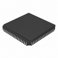
IC,MICROCONTROLLER,8-BIT,PIC CPU,CMOS,LDCC,84PIN,PLASTIC
Manufacturer
Microchip Technology
Series
PIC® 18Cr
Datasheets
1.PIC16F616T-ISL.pdf
(8 pages)
2.PIC18C601-IL.pdf
(320 pages)
3.PIC18C601-IL.pdf
(10 pages)
4.PIC18C601-IL.pdf
(10 pages)
Specifications of PIC18C801-I/L
Rohs Compliant
YES
Core Processor
PIC
Core Size
8-Bit
Speed
25MHz
Connectivity
EBI/EMI, I²C, SPI, UART/USART
Peripherals
Brown-out Detect/Reset, LVD, POR, PWM, WDT
Number Of I /o
37
Program Memory Type
ROMless
Ram Size
1.5K x 8
Voltage - Supply (vcc/vdd)
4.2 V ~ 5.5 V
Data Converters
A/D 12x10b
Oscillator Type
External
Operating Temperature
-40°C ~ 85°C
Package / Case
84-PLCC
Processor Series
PIC18C
Core
PIC
Data Bus Width
8 bit
Data Ram Size
1.5 KB
Interface Type
3-Wire, I2C, SPI, USART
Maximum Clock Frequency
25 MHz
Number Of Programmable I/os
47
Number Of Timers
1 x 16 bit
Operating Supply Voltage
2 V to 5.5 V
Maximum Operating Temperature
+ 85 C
Mounting Style
SMD/SMT
3rd Party Development Tools
52715-96, 52716-328, 52717-734, 52712-325, EWPIC18
Development Tools By Supplier
DV164005, ICE4000, DV164136
Minimum Operating Temperature
- 40 C
On-chip Adc
10 bit
Lead Free Status / RoHS Status
Lead free / RoHS Compliant
For Use With
AC164310 - MODULE SKT FOR PM3 84PLCCXLT84L1 - SOCKET TRANSITION ICE 84PLCCAC174012 - MODULE SKT PROMATEII 84PLCC
Eeprom Size
-
Program Memory Size
-
Lead Free Status / Rohs Status
Details
Other names
PIC18C801-I/LR
PIC18C801-I/LR
PIC18C801I/L
PIC18C801-I/LR
PIC18C801I/L
Available stocks
Company
Part Number
Manufacturer
Quantity
Price
Company:

Part Number:
PIC18C801-I/L
Manufacturer:
MICROCHIP
Quantity:
12 000
Company:
Part Number:
PIC18C801-I/L
Manufacturer:
Microchip Technology
Quantity:
10 000


11.2
A crystal oscillator circuit is built-in between pins T1OSI
(input) and T1OSO (amplifier output). It is enabled by
setting control bit T1OSCEN (T1CON register). The
oscillator is a low power oscillator rated up to 200 kHz.
It will continue to run during SLEEP. It is primarily
intended for a 32 kHz crystal. Table 11-1 shows the
capacitor selection for the Timer1 oscillator.
The user must provide a software time delay to ensure
proper start-up of the Timer1 oscillator.
TABLE 11-1:
11.3
The TMR1 Register pair (TMR1H:TMR1L) increments
from 0000h to FFFFh and rolls over to 0000h. The
TMR1 interrupt, if enabled, is generated on overflow,
which is latched in interrupt flag bit TMR1IF (PIR regis-
ters). This interrupt can be enabled/disabled by setting/
clearing TMR1 interrupt enable bit TMR1IE (PIE
registers).
32.768 kHz Epson C-001R32.768K-A
Note 1: Microchip suggests 33 pF as a starting
Osc Type
2001 Microchip Technology Inc.
LP
2: Higher capacitance increases the stability
3: Since each resonator/crystal has its own
4: Capacitor values are for design guidance
Timer1 Oscillator
Timer1 Interrupt
point in validating the oscillator circuit.
of the oscillator, but also increases the
start-up time.
characteristics, the user should consult the
resonator/crystal manufacturer for appro-
priate values of external components.
only.
Crystal to be Tested:
32 kHz
Freq
CAPACITOR SELECTION FOR
THE ALTERNATE
OSCILLATOR
TBD
C1
(1)
20 PPM
Advance Information
TBD
C2
(1)
11.4
If the CCP module is configured in Compare mode
to
(CCP1M3:CCP1M0 = 1011), this signal will reset
Timer1 and start an A/D conversion (if the A/D module
is enabled).
Timer1 must be configured for either Timer, or Synchro-
nized Counter mode, to take advantage of this feature.
If Timer1 is running in Asynchronous Counter mode,
this RESET operation may not work.
In the event that a write to Timer1 coincides with a special
event trigger from CCP1, the write will take precedence.
In this mode of operation, the CCPR1H:CCPR1L regis-
ters pair, effectively becomes the period register for
Timer1.
11.5
Timer1 can be configured for 16-bit reads and writes
(see Figure 11-2). When the RD16 control bit (T1CON
register) is set, the address for TMR1H is mapped to a
buffer register for the high byte of Timer1. A read from
TMR1L will load the contents of the high byte of Timer1
into the Timer1 high byte buffer. This provides the user
with the ability to accurately read all 16 bits of Timer1,
without having to determine whether a read of the high
byte followed by a read of the low byte is valid, due to
a rollover between reads.
A write to the high byte of Timer1 must also take place
through the TMR1H buffer register. Timer1 high byte is
updated with the contents of TMR1H when a write
occurs to TMR1L. This allows a user to write all 16-bits
to both the high and low bytes of Timer1 at once.
The high byte of Timer1 is not directly readable or writ-
able in this mode. All reads and writes must take place
through the Timer1 high byte buffer register. Writes to
TMR1H do not clear the Timer1 prescaler. The
prescaler is only cleared on writes to TMR1L.
Note:
generate
Resetting Timer1 using a CCP
Trigger Output
Timer1 16-Bit Read/Write Mode
The special event triggers from the CCP1
module will not set interrupt flag bit
TMR1IF (PIR registers).
PIC18C601/801
a
“special
DS39541A-page 133
event
trigger"
Related parts for PIC18C801-I/L
Image
Part Number
Description
Manufacturer
Datasheet
Request
R

Part Number:
Description:
IC, 8BIT MCU, PIC18F, 40MHZ, LCC-44
Manufacturer:
Microchip Technology
Datasheet:
Part Number:
Description:
IC, 8BIT MCU, PIC18LF, 40MHZ, PLCC-64
Manufacturer:
Microchip Technology
Datasheet:
Part Number:
Description:
IC, 8BIT MCU, PIC18F, 64MHZ, TQFP-80
Manufacturer:
Microchip Technology
Datasheet:

Part Number:
Description:
MCU, MPU & DSP Development Tools CAN/LIN PICtail Plus Daughter Board
Manufacturer:
Microchip Technology
Datasheet:

Part Number:
Description:
IC, 8BIT MCU, PIC18F, 64MHZ, DIP-40
Manufacturer:
Microchip Technology
Datasheet:

Part Number:
Description:
IC, 8BIT MCU, PIC18LF, 40MHZ, PLCC-64
Manufacturer:
Microchip Technology
Datasheet:
Part Number:
Description:
IC, 8BIT MCU, PIC18F, 64MHZ, TQFP-64
Manufacturer:
Microchip Technology
Part Number:
Description:
IC, 8BIT MCU, PIC18F, 64MHZ, TQFP-80
Manufacturer:
Microchip Technology

Part Number:
Description:
8KB, Flash, 768bytes-RAM, 36I/O, 8-bit Family,nanowatt XLP 40 UQFN 5x5x0.5mm TUB
Manufacturer:
Microchip Technology
Datasheet:
Part Number:
Description:
8KB, Flash, 768bytes-RAM, 36I/O, 8-bit Family,nanowatt XLP 40 UQFN 5x5x0.5mm TUB
Manufacturer:
Microchip Technology
Part Number:
Description:
16KB, Flash, 768bytes-RAM, 36I/O, 8-bit Family,nanowatt XLP 40 UQFN 5x5x0.5mm TU
Manufacturer:
Microchip Technology
Datasheet:
Part Number:
Description:
16KB, Flash, 768bytes-RAM, 36I/O, 8-bit Family,nanowatt XLP 40 UQFN 5x5x0.5mm TU
Manufacturer:
Microchip Technology
Part Number:
Description:
32KB, Flash, 1536bytes-RAM, 36I/O, 8-bit Family,nanowatt XLP 40 UQFN 5x5x0.5mm T
Manufacturer:
Microchip Technology
Datasheet:
Part Number:
Description:
32KB, Flash, 1536bytes-RAM, 36I/O, 8-bit Family,nanowatt XLP 40 UQFN 5x5x0.5mm T
Manufacturer:
Microchip Technology
Part Number:
Description:
64KB, Flash, 3968bytes-RAM, 36I/O, 8-bit Family,nanowatt XLP 40 UQFN 5x5x0.5mm T
Manufacturer:
Microchip Technology
Datasheet: