PIC18C801-I/L Microchip Technology, PIC18C801-I/L Datasheet - Page 198
PIC18C801-I/L
Manufacturer Part Number
PIC18C801-I/L
Description
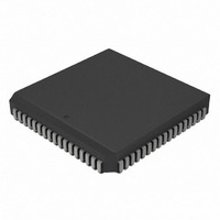
IC,MICROCONTROLLER,8-BIT,PIC CPU,CMOS,LDCC,84PIN,PLASTIC
Manufacturer
Microchip Technology
Series
PIC® 18Cr
Datasheets
1.PIC16F616T-ISL.pdf
(8 pages)
2.PIC18C601-IL.pdf
(320 pages)
3.PIC18C601-IL.pdf
(10 pages)
4.PIC18C601-IL.pdf
(10 pages)
Specifications of PIC18C801-I/L
Rohs Compliant
YES
Core Processor
PIC
Core Size
8-Bit
Speed
25MHz
Connectivity
EBI/EMI, I²C, SPI, UART/USART
Peripherals
Brown-out Detect/Reset, LVD, POR, PWM, WDT
Number Of I /o
37
Program Memory Type
ROMless
Ram Size
1.5K x 8
Voltage - Supply (vcc/vdd)
4.2 V ~ 5.5 V
Data Converters
A/D 12x10b
Oscillator Type
External
Operating Temperature
-40°C ~ 85°C
Package / Case
84-PLCC
Processor Series
PIC18C
Core
PIC
Data Bus Width
8 bit
Data Ram Size
1.5 KB
Interface Type
3-Wire, I2C, SPI, USART
Maximum Clock Frequency
25 MHz
Number Of Programmable I/os
47
Number Of Timers
1 x 16 bit
Operating Supply Voltage
2 V to 5.5 V
Maximum Operating Temperature
+ 85 C
Mounting Style
SMD/SMT
3rd Party Development Tools
52715-96, 52716-328, 52717-734, 52712-325, EWPIC18
Development Tools By Supplier
DV164005, ICE4000, DV164136
Minimum Operating Temperature
- 40 C
On-chip Adc
10 bit
Lead Free Status / RoHS Status
Lead free / RoHS Compliant
For Use With
AC164310 - MODULE SKT FOR PM3 84PLCCXLT84L1 - SOCKET TRANSITION ICE 84PLCCAC174012 - MODULE SKT PROMATEII 84PLCC
Eeprom Size
-
Program Memory Size
-
Lead Free Status / Rohs Status
Details
Other names
PIC18C801-I/LR
PIC18C801-I/LR
PIC18C801I/L
PIC18C801-I/LR
PIC18C801I/L
Available stocks
Company
Part Number
Manufacturer
Quantity
Price
Company:

Part Number:
PIC18C801-I/L
Manufacturer:
MICROCHIP
Quantity:
12 000
Company:
Part Number:
PIC18C801-I/L
Manufacturer:
Microchip Technology
Quantity:
10 000


PIC18C601/801
17.1
For the A/D converter to meet its specified accuracy,
the charge holding capacitor (C
to fully charge to the input channel voltage level. The
analog input model is shown in Figure 17-2. The
source impedance (R
switch (R
required to charge the capacitor C
switch (R
(V
at the analog input (due to pin leakage current). The
maximum recommended impedance for analog
sources is 2.5k . After the analog input channel is
selected (changed), this acquisition must be done
before the conversion can be started.
EQUATION 17-1:
EQUATION 17-2:
EXAMPLE 17-1: CALCULATING THE MINIMUM REQUIRED ACQUISITION TIME
DS39541A-page 198
T
T
Temperature coefficient is only required for temperatures > 25 C.
T
T
T
ACQ
V
or
T
DD
Note:
ACQ
ACQ
C
ACQ
C
HOLD
). The source impedance affects the offset voltage
=
=
A/D Acquisition Requirements
SS
SS
=
=
=
=
When the conversion is started, the hold-
ing capacitor is disconnected from the
input pin.
) impedance varies over the device voltage
) impedance directly affect the time
Amplifier Settling Time +
Holding Capacitor Charging Time +
Temperature Coefficient
T
=
=
AMP
T
2 s + T
-C
-120 pF (1 k + 7 k + 2.5 k ) ln(0.0004885)
-120 pF (10.5 k ) ln(0.0004885)
-1.26 s (-7.6241)
9.61 s
2 s + 9.61 s + [(50 C - 25 C)(0.05 s/ C)]
11.61 s + 1.25 s
12.86 s
AMP
(V
-(120 pF)(1 k + R
HOLD
+ T
REF
C
+ T
ACQUISITION TIME
A/D MINIMUM CHARGING TIME
S
+ T
- (V
C
) and the internal sampling
(R
C
+ [(Temp - 25 C)(0.05 s/ C)]
IC
COFF
+ T
REF
+ R
COFF
/2048)) • (1 - e
HOLD
SS
HOLD
+ R
SS
) must be allowed
+ R
S
. The sampling
) ln(1/2047)
S
) ln(1/2047)
Advance Information
(-Tc/C
HOLD
(R
IC
+ R
SS
+ R
To
Equation 17-1 may be used. This equation assumes
that 1/2 LSb error is used (1024 steps for the A/D). The
1/2 LSb error is the maximum error allowed for the A/D
to meet its specified resolution.
Example 17-1 shows the calculation of the minimum
required acquisition time T
based on the following application system assumptions:
C
Rs
Conversion Error
V
Temperature
V
S
HOLD
DD
HOLD
))
)
calculate
the
=
=
=
=
=
minimum
2001 Microchip Technology Inc.
120 pF
2.5 k
1/2 LSb
5V
50 C (system max.)
0V @ time = 0
ACQ
. This calculation is
Rss = 7 k
acquisition
time,
Related parts for PIC18C801-I/L
Image
Part Number
Description
Manufacturer
Datasheet
Request
R

Part Number:
Description:
IC, 8BIT MCU, PIC18F, 40MHZ, LCC-44
Manufacturer:
Microchip Technology
Datasheet:
Part Number:
Description:
IC, 8BIT MCU, PIC18LF, 40MHZ, PLCC-64
Manufacturer:
Microchip Technology
Datasheet:
Part Number:
Description:
IC, 8BIT MCU, PIC18F, 64MHZ, TQFP-80
Manufacturer:
Microchip Technology
Datasheet:

Part Number:
Description:
MCU, MPU & DSP Development Tools CAN/LIN PICtail Plus Daughter Board
Manufacturer:
Microchip Technology
Datasheet:

Part Number:
Description:
IC, 8BIT MCU, PIC18F, 64MHZ, DIP-40
Manufacturer:
Microchip Technology
Datasheet:

Part Number:
Description:
IC, 8BIT MCU, PIC18LF, 40MHZ, PLCC-64
Manufacturer:
Microchip Technology
Datasheet:
Part Number:
Description:
IC, 8BIT MCU, PIC18F, 64MHZ, TQFP-64
Manufacturer:
Microchip Technology
Part Number:
Description:
IC, 8BIT MCU, PIC18F, 64MHZ, TQFP-80
Manufacturer:
Microchip Technology

Part Number:
Description:
8KB, Flash, 768bytes-RAM, 36I/O, 8-bit Family,nanowatt XLP 40 UQFN 5x5x0.5mm TUB
Manufacturer:
Microchip Technology
Datasheet:
Part Number:
Description:
8KB, Flash, 768bytes-RAM, 36I/O, 8-bit Family,nanowatt XLP 40 UQFN 5x5x0.5mm TUB
Manufacturer:
Microchip Technology
Part Number:
Description:
16KB, Flash, 768bytes-RAM, 36I/O, 8-bit Family,nanowatt XLP 40 UQFN 5x5x0.5mm TU
Manufacturer:
Microchip Technology
Datasheet:
Part Number:
Description:
16KB, Flash, 768bytes-RAM, 36I/O, 8-bit Family,nanowatt XLP 40 UQFN 5x5x0.5mm TU
Manufacturer:
Microchip Technology
Part Number:
Description:
32KB, Flash, 1536bytes-RAM, 36I/O, 8-bit Family,nanowatt XLP 40 UQFN 5x5x0.5mm T
Manufacturer:
Microchip Technology
Datasheet:
Part Number:
Description:
32KB, Flash, 1536bytes-RAM, 36I/O, 8-bit Family,nanowatt XLP 40 UQFN 5x5x0.5mm T
Manufacturer:
Microchip Technology
Part Number:
Description:
64KB, Flash, 3968bytes-RAM, 36I/O, 8-bit Family,nanowatt XLP 40 UQFN 5x5x0.5mm T
Manufacturer:
Microchip Technology
Datasheet: