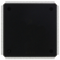
MCF5407AI220 Freescale Semiconductor, MCF5407AI220 Datasheet - Page 152

MCF5407AI220
Manufacturer Part Number
MCF5407AI220
Description
IC MPU 32B 220MHZ COLDF 208-FQFP
Manufacturer
Freescale Semiconductor
Series
MCF540xr
Specifications of MCF5407AI220
Core Processor
Coldfire V4
Core Size
32-Bit
Speed
220MHz
Connectivity
EBI/EMI, I²C, UART/USART
Peripherals
DMA, WDT
Number Of I /o
16
Program Memory Type
ROMless
Ram Size
4K x 8
Voltage - Supply (vcc/vdd)
1.65 V ~ 3.6 V
Oscillator Type
External
Operating Temperature
0°C ~ 70°C
Package / Case
208-FQFP
Maximum Clock Frequency
220 MHz
Operating Supply Voltage
1.8 V, 3.3 V
Maximum Operating Temperature
+ 105 C
Mounting Style
SMD/SMT
Minimum Operating Temperature
0 C
Program Memory Size
24KB
Cpu Speed
220MHz
Embedded Interface Type
I2C, UART
Digital Ic Case Style
FQFP
No. Of Pins
208
Supply Voltage Range
3.3V
Rohs Compliant
Yes
For Use With
M5407C3 - KIT EVAL FOR MCF5407 W/ETHERNET
Lead Free Status / RoHS Status
Lead free / RoHS Compliant
Eeprom Size
-
Program Memory Size
-
Data Converters
-
Lead Free Status / Rohs Status
Lead free / RoHS Compliant
Available stocks
Company
Part Number
Manufacturer
Quantity
Price
Company:
Part Number:
MCF5407AI220
Manufacturer:
freescaie
Quantity:
6
Company:
Part Number:
MCF5407AI220
Manufacturer:
Freescale Semiconductor
Quantity:
135
Company:
Part Number:
MCF5407AI220
Manufacturer:
FREESCALE
Quantity:
1 831
Company:
Part Number:
MCF5407AI220
Manufacturer:
Freescale Semiconductor
Quantity:
10 000
- Current page: 152 of 546
- Download datasheet (7Mb)
Cache Operation Summary
4.12.2 Data Cache State Transitions
Using the V and M bits, the data cache supports a line-based protocol allowing individual
cache lines to be invalid, valid, or modified. To maintain memory coherency, the data cache
supports both write-through and copyback modes, specified by the corresponding
ACR[CM], or CACR[DDCM] if no ACR matches.
Read or write misses to copyback regions cause the cache controller to read a cache line
from memory into the cache. If available, tag and data from memory update an invalid line
in the selected set. The line state then changes from invalid to valid by setting the V bit. If
all lines in the row are already valid or modified, the pseudo-round-robin replacement
algorithm selects one of the four lines and replaces the tag and data. Before replacement,
modified lines are temporarily buffered and later copied back to memory after the new line
has been read from memory.
Figure 4-13 shows the three possible data cache line states and possible processor-initiated
transitions for memory configured as copyback. Transitions are labeled with a capital letter
indicating the previous state and a number indicating the specific case listed in Table 4-7.
4-28
Cache
invalidate
Cache
push
Access
CI5—DCINVA
CI6—CPUSHL & DDPI
CI7—CPUSHL & DDPI
Table 4-6. Instruction Cache Line State Transitions (Continued)
II5 No action;
II6,
II7
Figure 4-13. Data Cache Line State Diagram—Copyback Mode
stay in invalid state.
No action;
stay in invalid state.
CD5—DCINVA
CD6—CPUSHL & DDPI
Invalid
Invalid (V = 0)
V = 0
CD2—CPU read hit
CD3—CPU write miss
CD4—CPU write hit
CI3—CPU
write miss
MCF5407 User’s Manual
CI1—CPU read miss
CV5—DCINVA
CV6—CPUSHL & DDPI
CD7—CPUSHL
& DDPI
Modified
M = 1
V = 1
Current State
CD1—CPU
read miss
IV5 No action;
IV6 No action;
IV7 No action;
go to invalid state.
go to invalid state.
stay in valid state.
CV3—CPU write miss
CV4—CPU write hit
Valid (V = 1)
M = 0
V = 1
Valid
CV1—CPU read miss
CV2—CPU read hit
CV7—CPUSHL & DDPI
Related parts for MCF5407AI220
Image
Part Number
Description
Manufacturer
Datasheet
Request
R
Part Number:
Description:
Mcf5407 Coldfire Integrated Microprocessor User
Manufacturer:
Freescale Semiconductor, Inc
Datasheet:
Part Number:
Description:
Manufacturer:
Freescale Semiconductor, Inc
Datasheet:
Part Number:
Description:
Manufacturer:
Freescale Semiconductor, Inc
Datasheet:
Part Number:
Description:
Manufacturer:
Freescale Semiconductor, Inc
Datasheet:
Part Number:
Description:
Manufacturer:
Freescale Semiconductor, Inc
Datasheet:
Part Number:
Description:
Manufacturer:
Freescale Semiconductor, Inc
Datasheet:
Part Number:
Description:
Manufacturer:
Freescale Semiconductor, Inc
Datasheet:
Part Number:
Description:
Manufacturer:
Freescale Semiconductor, Inc
Datasheet:
Part Number:
Description:
Manufacturer:
Freescale Semiconductor, Inc
Datasheet:
Part Number:
Description:
Manufacturer:
Freescale Semiconductor, Inc
Datasheet:
Part Number:
Description:
Manufacturer:
Freescale Semiconductor, Inc
Datasheet:
Part Number:
Description:
Manufacturer:
Freescale Semiconductor, Inc
Datasheet:
Part Number:
Description:
Manufacturer:
Freescale Semiconductor, Inc
Datasheet:
Part Number:
Description:
Manufacturer:
Freescale Semiconductor, Inc
Datasheet:
Part Number:
Description:
Manufacturer:
Freescale Semiconductor, Inc
Datasheet:


