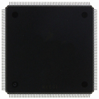
MCF5407AI220 Freescale Semiconductor, MCF5407AI220 Datasheet - Page 246

MCF5407AI220
Manufacturer Part Number
MCF5407AI220
Description
IC MPU 32B 220MHZ COLDF 208-FQFP
Manufacturer
Freescale Semiconductor
Series
MCF540xr
Specifications of MCF5407AI220
Core Processor
Coldfire V4
Core Size
32-Bit
Speed
220MHz
Connectivity
EBI/EMI, I²C, UART/USART
Peripherals
DMA, WDT
Number Of I /o
16
Program Memory Type
ROMless
Ram Size
4K x 8
Voltage - Supply (vcc/vdd)
1.65 V ~ 3.6 V
Oscillator Type
External
Operating Temperature
0°C ~ 70°C
Package / Case
208-FQFP
Maximum Clock Frequency
220 MHz
Operating Supply Voltage
1.8 V, 3.3 V
Maximum Operating Temperature
+ 105 C
Mounting Style
SMD/SMT
Minimum Operating Temperature
0 C
Program Memory Size
24KB
Cpu Speed
220MHz
Embedded Interface Type
I2C, UART
Digital Ic Case Style
FQFP
No. Of Pins
208
Supply Voltage Range
3.3V
Rohs Compliant
Yes
For Use With
M5407C3 - KIT EVAL FOR MCF5407 W/ETHERNET
Lead Free Status / RoHS Status
Lead free / RoHS Compliant
Eeprom Size
-
Program Memory Size
-
Data Converters
-
Lead Free Status / Rohs Status
Lead free / RoHS Compliant
Available stocks
Company
Part Number
Manufacturer
Quantity
Price
Company:
Part Number:
MCF5407AI220
Manufacturer:
freescaie
Quantity:
6
Company:
Part Number:
MCF5407AI220
Manufacturer:
Freescale Semiconductor
Quantity:
135
Company:
Part Number:
MCF5407AI220
Manufacturer:
FREESCALE
Quantity:
1 831
Company:
Part Number:
MCF5407AI220
Manufacturer:
Freescale Semiconductor
Quantity:
10 000
- Current page: 246 of 546
- Download datasheet (7Mb)
I
next byte data receiving. In slave mode, the same function is available after it is addressed.
8.6 I
The following examples show programming for initialization, signalling START,
post-transfer software response, signalling STOP, and generating a repeated START.
8.6.1 Initialization Sequence
Before the interface can transfer serial data, registers must be initialized, as follows:
8.6.2 Generation of START
After completion of the initialization procedure, serial data can be transmitted by selecting
the master transmitter mode. On a multiple-master bus system, IBSR[IBB] must be tested
to determine whether the serial bus is free. If the bus is free (IBB = 0), the START signal
and the first byte (the slave address) can be sent. The data written to the data register
comprises the address of the desired slave and the lsb indicates the transfer direction.
8-10
2
C Programming Examples
1. Set IFDR[IC] to obtain SCL frequency from the system bus clock. See
2. Update the IADR to define its slave address.
3. Set I2CR[IEN] to enable the I
4. Modify the I2CR to select master/slave mode, transmit/receive mode, and
Section 8.5.2, “I2C Frequency Divider Register (IFDR).”
interrupt-enable or not.
2
Address
C Programming Examples
Reset
Field
R/W
If IBSR[IBB] when the I
following code sequence before proceeding with normal
initialization code. This issues a STOP command to the slave
device, placing it in idle state as if it were just power-cycled on.
I2CR = 0x0
I2CR = 0xA
dummy read of I2DR
IBSR = 0x0
I2CR = 0x0
7
Figure 8-9. I
6
MCF5407 User’s Manual
5
2
2
C bus interface system.
C Data I/O Register (I2DR)
2
C bus module is enabled, execute the
NOTE:
MBAR + 0x290
4
0000_0000
Read/Write
D
3
2
1
0
Related parts for MCF5407AI220
Image
Part Number
Description
Manufacturer
Datasheet
Request
R
Part Number:
Description:
Mcf5407 Coldfire Integrated Microprocessor User
Manufacturer:
Freescale Semiconductor, Inc
Datasheet:
Part Number:
Description:
Manufacturer:
Freescale Semiconductor, Inc
Datasheet:
Part Number:
Description:
Manufacturer:
Freescale Semiconductor, Inc
Datasheet:
Part Number:
Description:
Manufacturer:
Freescale Semiconductor, Inc
Datasheet:
Part Number:
Description:
Manufacturer:
Freescale Semiconductor, Inc
Datasheet:
Part Number:
Description:
Manufacturer:
Freescale Semiconductor, Inc
Datasheet:
Part Number:
Description:
Manufacturer:
Freescale Semiconductor, Inc
Datasheet:
Part Number:
Description:
Manufacturer:
Freescale Semiconductor, Inc
Datasheet:
Part Number:
Description:
Manufacturer:
Freescale Semiconductor, Inc
Datasheet:
Part Number:
Description:
Manufacturer:
Freescale Semiconductor, Inc
Datasheet:
Part Number:
Description:
Manufacturer:
Freescale Semiconductor, Inc
Datasheet:
Part Number:
Description:
Manufacturer:
Freescale Semiconductor, Inc
Datasheet:
Part Number:
Description:
Manufacturer:
Freescale Semiconductor, Inc
Datasheet:
Part Number:
Description:
Manufacturer:
Freescale Semiconductor, Inc
Datasheet:
Part Number:
Description:
Manufacturer:
Freescale Semiconductor, Inc
Datasheet:


