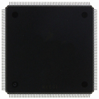
MCF5407AI220 Freescale Semiconductor, MCF5407AI220 Datasheet - Page 37

MCF5407AI220
Manufacturer Part Number
MCF5407AI220
Description
IC MPU 32B 220MHZ COLDF 208-FQFP
Manufacturer
Freescale Semiconductor
Series
MCF540xr
Specifications of MCF5407AI220
Core Processor
Coldfire V4
Core Size
32-Bit
Speed
220MHz
Connectivity
EBI/EMI, I²C, UART/USART
Peripherals
DMA, WDT
Number Of I /o
16
Program Memory Type
ROMless
Ram Size
4K x 8
Voltage - Supply (vcc/vdd)
1.65 V ~ 3.6 V
Oscillator Type
External
Operating Temperature
0°C ~ 70°C
Package / Case
208-FQFP
Maximum Clock Frequency
220 MHz
Operating Supply Voltage
1.8 V, 3.3 V
Maximum Operating Temperature
+ 105 C
Mounting Style
SMD/SMT
Minimum Operating Temperature
0 C
Program Memory Size
24KB
Cpu Speed
220MHz
Embedded Interface Type
I2C, UART
Digital Ic Case Style
FQFP
No. Of Pins
208
Supply Voltage Range
3.3V
Rohs Compliant
Yes
For Use With
M5407C3 - KIT EVAL FOR MCF5407 W/ETHERNET
Lead Free Status / RoHS Status
Lead free / RoHS Compliant
Eeprom Size
-
Program Memory Size
-
Data Converters
-
Lead Free Status / Rohs Status
Lead free / RoHS Compliant
Available stocks
Company
Part Number
Manufacturer
Quantity
Price
Company:
Part Number:
MCF5407AI220
Manufacturer:
freescaie
Quantity:
6
Company:
Part Number:
MCF5407AI220
Manufacturer:
Freescale Semiconductor
Quantity:
135
Company:
Part Number:
MCF5407AI220
Manufacturer:
FREESCALE
Quantity:
1 831
Company:
Part Number:
MCF5407AI220
Manufacturer:
Freescale Semiconductor
Quantity:
10 000
- Current page: 37 of 546
- Download datasheet (7Mb)
• Part III, “Peripheral Module,” describes the operation and configuration of the
• Part IV, “Hardware Interface,” provides a pinout and both electrical and functional
MCF5407 DMA, timer, UART, and parallel port modules, and describes how they
interface with the system integration unit, described in Part II.
— Chapter 12, “DMA Controller Module,” provides an overview of the DMA
— Chapter 13, “Timer Module,” describes configuration and operation of the two
— Chapter 14, “UART Modules,” describes the use of the universal
— Chapter 15, “Parallel Port (General-Purpose I/O),” describes the operation and
descriptions of the MCF5407 signals. It also describes how these signals interact to
support the variety of bus operations shown in timing diagrams.
— Chapter 16, “Mechanical Data,” provides a functional pin listing and package
— Chapter 17, “Signal Descriptions,” provides an alphabetical listing of MCF5407
— Chapter 18, “Bus Operation,” describes data transfers, error conditions, bus
— Chapter 19, “IEEE 1149.1 Test Access Port (JTAG),” describes configuration
controller component of the SIM. It begins with a general description and brief
glossary, and includes a description of signals involved in DRAM operations.
The remainder of the chapter is divided between descriptions of asynchronous
and synchronous operations.
controller module and describes in detail its signals and registers. The latter
sections of this chapter describe operations, features, and supported data transfer
modes in detail, showing timing diagrams for various operations.
general-purpose timer modules, timer 0 and timer 1. It includes programming
examples.
asynchronous/synchronous receiver/transmitters (UARTs) implemented on the
MCF5407 and includes programming examples. Particular attention is given to
the UART1 implementation of a synchronous interface that provides a controller
for an 8- or 16-bit CODEC interface and an audio CODEC ‘97 (AC ’97) digital
interface.
programming model of the parallel port pin assignment, direction-control, and
data registers. It includes a code example for setting up the parallel port.
diagram for the MCF5407.
signals. This chapter describes the MCF5407 signals. In particular, it shows
which are inputs or outputs, how they are multiplexed, which signals require
pull-up resistors, and the state of each signal at reset.
arbitration, and reset operations. It describes transfers initiated by the MCF5407
and by an external bus master, and includes detailed timing diagrams showing
the interaction of signals in supported bus operations. Note that Chapter 11,
“Synchronous/Asynchronous DRAM Controller Module,” describes DRAM
cycles.
and operation of the MCF5407 JTAG test implementation. It describes the use of
JTAG instructions and how to disable JTAG functionality.
About This Book
Organization
xxxvii
Related parts for MCF5407AI220
Image
Part Number
Description
Manufacturer
Datasheet
Request
R
Part Number:
Description:
Mcf5407 Coldfire Integrated Microprocessor User
Manufacturer:
Freescale Semiconductor, Inc
Datasheet:
Part Number:
Description:
Manufacturer:
Freescale Semiconductor, Inc
Datasheet:
Part Number:
Description:
Manufacturer:
Freescale Semiconductor, Inc
Datasheet:
Part Number:
Description:
Manufacturer:
Freescale Semiconductor, Inc
Datasheet:
Part Number:
Description:
Manufacturer:
Freescale Semiconductor, Inc
Datasheet:
Part Number:
Description:
Manufacturer:
Freescale Semiconductor, Inc
Datasheet:
Part Number:
Description:
Manufacturer:
Freescale Semiconductor, Inc
Datasheet:
Part Number:
Description:
Manufacturer:
Freescale Semiconductor, Inc
Datasheet:
Part Number:
Description:
Manufacturer:
Freescale Semiconductor, Inc
Datasheet:
Part Number:
Description:
Manufacturer:
Freescale Semiconductor, Inc
Datasheet:
Part Number:
Description:
Manufacturer:
Freescale Semiconductor, Inc
Datasheet:
Part Number:
Description:
Manufacturer:
Freescale Semiconductor, Inc
Datasheet:
Part Number:
Description:
Manufacturer:
Freescale Semiconductor, Inc
Datasheet:
Part Number:
Description:
Manufacturer:
Freescale Semiconductor, Inc
Datasheet:
Part Number:
Description:
Manufacturer:
Freescale Semiconductor, Inc
Datasheet:


