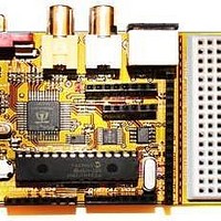
Chameleon-PIC Nurve Networks, Chameleon-PIC Datasheet - Page 59

Chameleon-PIC
Manufacturer Part Number
Chameleon-PIC
Description
MCU, MPU & DSP Development Tools PIC24 & PROPELLER DEV SYSTEM (SBC)
Manufacturer
Nurve Networks
Datasheet
1.CHAMELEON-PIC.pdf
(263 pages)
Specifications of Chameleon-PIC
Processor To Be Evaluated
PIC24
Data Bus Width
16 bit
Interface Type
USB, VGA, PS/2, I2C, ISP, SPI
Operating Supply Voltage
3.3 V, 5 V
Lead Free Status / RoHS Status
Lead free / RoHS Compliant
- Current page: 59 of 263
- Download datasheet (12Mb)
a single LOW start bit (35 μs) followed by 8 data bits (70us each), a parity bit, and finally a HIGH stop bit. Data should
be sampled by the host computer on the data line on the falling edge of the CLOCK line (driven by keyboard). Below is
the general algorithm for reading the keyboard.
12.1.2 Keyboard Read Algorithm
The read algorithm makes the assumption that the main host has been forcing the keyboard to buffer the last key. This is
accomplished by holding CLOCK LOW. Once the host releases the keyboard, then the keyboard will start clocking the
clock line and drop the DATA line with a start bit if there was a key in the buffer, else the DATA line will stay HIGH. So
the following steps are after the host releases the keyboard and is trying to determine by means of polling if there is a key
in the keyboard buffer.
Step 1: Delay 5 μs to allow hold on CLOCK line to release and keyboard to send buffered scan code.
Step 2 (Start of frame): If both CLOCK and DATA are low (start bit) then enter into read loop, else return, no key present.
Step 3 (Start of data): Wait until clock goes high...
Step 4 (Read data): Read data bits loop.
Step 5: (Read parity and Stop Bits): Lastly the parity and Stop Bits must be read.
And that’s it! Of course, if you want to be strict then you should read the parity and stop bit, but you don’t need to unless
you want to perform error correction.
12.1.3 Keyboard Write Algorithm
The process of sending commands to the keyboard or “writing” to the keyboard is identical to that when reading. The
protocol is the same except the host initiates the conversation. Then the keyboard will actually do the clocking while the
host pulls on the data line at the appropriate times. The sequence is as follows:
// pseudo code
for (t = 0; t <= 7; t++) {
wait for CLOCK to go low...
delay 5 μs to center sample
bit(t) = DATA;
} // end for
NOTE
Both the keyboard and mouse use an “odd parity” scheme for error detection. Odd
parity is HIGH when the number of 1’s in a string is ODD, LOW otherwise. Even parity is
HIGH when the number of 1’s in a string is EVEN, LOW otherwise. Note that parity only
tells us there is an error, but not how to correct it, or where it was. You simply have to
re-transmit the data.
Figure 12.3 – Keyboard Serial Data Packet.
© 2009 NURVE NETWORKS LLC “Exploring the Chameleon PIC 16-Bit”
59
Related parts for Chameleon-PIC
Image
Part Number
Description
Manufacturer
Datasheet
Request
R

Part Number:
Description:
MCU, MPU & DSP Development Tools AVR8 VIDEO GAME DEV SYSTEM (SBC)
Manufacturer:
Nurve Networks

Part Number:
Description:
MCU, MPU & DSP Development Tools PIC24 VIDEO GAME DEV SYSTEM (SBC)
Manufacturer:
Nurve Networks

Part Number:
Description:
MCU, MPU & DSP Development Tools AVR8 & PROPELLER DEV SYSTEM (SBC)
Manufacturer:
Nurve Networks
Datasheet:


