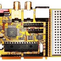
Chameleon-PIC Nurve Networks, Chameleon-PIC Datasheet - Page 34

Chameleon-PIC
Manufacturer Part Number
Chameleon-PIC
Description
MCU, MPU & DSP Development Tools PIC24 & PROPELLER DEV SYSTEM (SBC)
Manufacturer
Nurve Networks
Datasheet
1.CHAMELEON-PIC.pdf
(263 pages)
Specifications of Chameleon-PIC
Processor To Be Evaluated
PIC24
Data Bus Width
16 bit
Interface Type
USB, VGA, PS/2, I2C, ISP, SPI
Operating Supply Voltage
3.3 V, 5 V
Lead Free Status / RoHS Status
Lead free / RoHS Compliant
- Current page: 34 of 263
- Download datasheet (12Mb)
5.0 Serial USB UART Programming Port
The Propeller chip as well as the PIC can also be programmed via the serial USB UART. The Propeller uses serial to
communicate as default; however, the PIC uses serial only when there is a “bootloader” programmed into the PIC that
“listens” to the serial port and there is a protocol in place as well as tool on the other end that follows the protocol
agreement to re-program the FLASH. Therefore, the native method to re-program the Propeller is via the serial
connection, but the PIC is typically re-programmed via the ISP port, thus the serial re-programming is a trick/hack that is
simply supported by a bootloader that supports it. With that in mind, the next section covers the USB UART design, but
before we take a look at that there is one sub-section of the design we need to look at and that’s the serial port “routing”
switch shown in Figure 5.1.
The USB UART has a standard TX/RX serial line pair. But, there are two targets we need these to go to; the Propeller
chip and the PIC, thus, we just can’t connect them in parallel since if both the Propeller and PIC try to transmit at the
same time then there will obviously be a problem. Moreover, the impedance reflected by tying the TX/RX to both devices
is not desired. Thus, a mechanical switch SW3 is used to switch the RX lines which at very least are needed to allow both
devices to share the serial port. Therefore, when you want to talk to the Propeller chip via the USB serial port you must
place the switch into the Propeller mode (UP), and similarly when you want to talk to the PIC you must put the switch into
the PIC mode (DOWN).
TIP
Typically, you will leave the switch in down (PIC mode) most of the time unless you are
constantly re-programming the driver on the Propeller chip.
Figure 5.1 – Serial port routing/selector switch.
© 2009 NURVE NETWORKS LLC “Exploring the Chameleon PIC 16-Bit”
34
Related parts for Chameleon-PIC
Image
Part Number
Description
Manufacturer
Datasheet
Request
R

Part Number:
Description:
MCU, MPU & DSP Development Tools AVR8 VIDEO GAME DEV SYSTEM (SBC)
Manufacturer:
Nurve Networks

Part Number:
Description:
MCU, MPU & DSP Development Tools PIC24 VIDEO GAME DEV SYSTEM (SBC)
Manufacturer:
Nurve Networks

Part Number:
Description:
MCU, MPU & DSP Development Tools AVR8 & PROPELLER DEV SYSTEM (SBC)
Manufacturer:
Nurve Networks
Datasheet:


