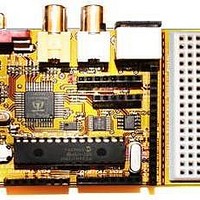
Chameleon-PIC Nurve Networks, Chameleon-PIC Datasheet - Page 73

Chameleon-PIC
Manufacturer Part Number
Chameleon-PIC
Description
MCU, MPU & DSP Development Tools PIC24 & PROPELLER DEV SYSTEM (SBC)
Manufacturer
Nurve Networks
Datasheet
1.CHAMELEON-PIC.pdf
(263 pages)
Specifications of Chameleon-PIC
Processor To Be Evaluated
PIC24
Data Bus Width
16 bit
Interface Type
USB, VGA, PS/2, I2C, ISP, SPI
Operating Supply Voltage
3.3 V, 5 V
Lead Free Status / RoHS Status
Lead free / RoHS Compliant
- Current page: 73 of 263
- Download datasheet (12Mb)
After reading all these documents you should have a fairly good grasp of PWM techniques. More or less, PWM is really a
method of digital to analog conversion using a single bit output along with a low-pass filter that acts as an “averaging” or
“integration” device. A PWM signal is at fixed output frequency usually many times the highest frequency you want to
synthesis, for example a good rule of thumb is that the PWM signal should be 10-100x greater than the frequencies you
want to synthesis. Also, the PWM period is fixed, the modulation of information in the PWM signal is in the duty cycle of
the signal. Recall, duty cycle is defined as:
For example, say we had a 1KHz signal, this means the period is 1/1KHz = 1mS = 1000 μs. Now, let’s say we are talking
about square waves in a digital system with a HIGH of 5V and a LOW of 0V. Furthermore, let’s say that the duty cycle is
20%, what would the final waveform look like? Figure 14.4(a) depicts this. As you can see the waveform is HIGH 20% of
the total period or 200 μs, and the waveform is LOW 800 μs. Therefore, if you were to average this signal f(t) over time
you would find that the average is simply the area under the HIGH part divided by the total AREA of the waveform which
is:
This is a VERY interesting result, by just varying the time we pulse a digital output HIGH we can create an analog voltage!
Thus, we can modulate the analog voltage in any shape we wish to create a final waveform of any shape we want;
sounds, explosions, voices, etc. plus since this is all digital we can synthesis as many channels as we wish since at the
end of the day we need only a single bit as the output. Figure 14.4(b) shows another PWM like technique where instead of
modulating the duty cycle, instead complete 50% duty cycle pulses are sent, but they are interspersed with 0% duty
cycles as a function of time. If the rate of these “pulses” is high enough, they too create an “average” voltage over time. In
Figure 14.4(b) there are 10 total cycles and in 2 of them we have 50% duty cycles for a total analog voltage per 10 clocks
of:
Duty Cycle = Time Waveform is HIGH / Total Period of Waveform
Average Signal @ 20% duty cycle = (5V)* [ (200 μs) / (1000 μs ) ] = 1.00V.
Average Signal @ 20% duty cycle = (5V)* (50%)*[ (100 ns) / (1000 ns ) ] = 0.5V.
Figure 14.4 - Duty cycle modes.
© 2009 NURVE NETWORKS LLC “Exploring the Chameleon PIC 16-Bit”
73
Related parts for Chameleon-PIC
Image
Part Number
Description
Manufacturer
Datasheet
Request
R

Part Number:
Description:
MCU, MPU & DSP Development Tools AVR8 VIDEO GAME DEV SYSTEM (SBC)
Manufacturer:
Nurve Networks

Part Number:
Description:
MCU, MPU & DSP Development Tools PIC24 VIDEO GAME DEV SYSTEM (SBC)
Manufacturer:
Nurve Networks

Part Number:
Description:
MCU, MPU & DSP Development Tools AVR8 & PROPELLER DEV SYSTEM (SBC)
Manufacturer:
Nurve Networks
Datasheet:


