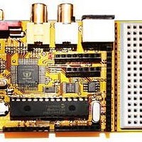
Chameleon-PIC Nurve Networks, Chameleon-PIC Datasheet - Page 157

Chameleon-PIC
Manufacturer Part Number
Chameleon-PIC
Description
MCU, MPU & DSP Development Tools PIC24 & PROPELLER DEV SYSTEM (SBC)
Manufacturer
Nurve Networks
Datasheet
1.CHAMELEON-PIC.pdf
(263 pages)
Specifications of Chameleon-PIC
Processor To Be Evaluated
PIC24
Data Bus Width
16 bit
Interface Type
USB, VGA, PS/2, I2C, ISP, SPI
Operating Supply Voltage
3.3 V, 5 V
Lead Free Status / RoHS Status
Lead free / RoHS Compliant
- Current page: 157 of 263
- Download datasheet (12Mb)
The use of the circular buffers means that you can send and receive a byte in only 8 clocks rather than clocking out 8-bits
to send, then clocking in 8-bits to receive. Of course, in some cases the data clocked out or in is “dummy” data, meaning
when you write data and you are not expecting a result the data you clock in is garbage and you can throw it away.
Likewise when you do a SPI read, typically you would put a $00 or $FF in the transmit buffer as dummy data since
something has to be sent and it might as well be predictable.
Sending bytes with SPI is similar to the serial RS-232 protocol, you place a bit of information on the transmit line, then
strobe the clock line (of course RS-232 has no clock). As you do this, you also need to read the receive line since data is
being transmitted in both directions. This is simple enough, but SPI protocol has some very specific details attached to it
about when signals should be read and written that is, on the rising or falling edge of the clock as well as the polarity of
the clock signal. This way there is no confusion about edge, level, or phase of the signals. These various modes of
operation are logically called the SPI modes and are listed in Table 19.1 below:
Mode Descriptions
Mode 0 – The clock is active when HIGH. Data is read on the rising edge of the clock. Data is written on the falling
Mode 1 – The clock is active when HIGH. Data is read on the falling edge of the clock. Data is written on the rising
Mode 2 – The clock is active when LOW. Data is read on the rising edge of the clock. Data is written on the falling
Mode 3 – The clock is active when LOW. Data is read on the falling edge of the clock. Data is written on the rising
Note: Most SPI slaves default to mode 0, so typically this mode is what is used to initiate communications with a SPI
device.
edge of the clock (default mode for most SPI applications).
edge of the clock.
edge of the clock.
edge of the clock.
Mode #
0
1
2
3
CPOL (Clock Polarity)
0
0
1
1
Figure 19.2 – Circular SPI buffers.
Table 19.1 – SPI clocking modes.
© 2009 NURVE NETWORKS LLC “Exploring the Chameleon PIC 16-Bit”
CPHA (Clock Phase)
0
1
0
1
157
Related parts for Chameleon-PIC
Image
Part Number
Description
Manufacturer
Datasheet
Request
R

Part Number:
Description:
MCU, MPU & DSP Development Tools AVR8 VIDEO GAME DEV SYSTEM (SBC)
Manufacturer:
Nurve Networks

Part Number:
Description:
MCU, MPU & DSP Development Tools PIC24 VIDEO GAME DEV SYSTEM (SBC)
Manufacturer:
Nurve Networks

Part Number:
Description:
MCU, MPU & DSP Development Tools AVR8 & PROPELLER DEV SYSTEM (SBC)
Manufacturer:
Nurve Networks
Datasheet:


