Chameleon-PIC Nurve Networks, Chameleon-PIC Datasheet - Page 16
Chameleon-PIC
Manufacturer Part Number
Chameleon-PIC
Description
MCU, MPU & DSP Development Tools PIC24 & PROPELLER DEV SYSTEM (SBC)
Manufacturer
Nurve Networks
Datasheet
1.CHAMELEON-PIC.pdf
(263 pages)
Specifications of Chameleon-PIC
Processor To Be Evaluated
PIC24
Data Bus Width
16 bit
Interface Type
USB, VGA, PS/2, I2C, ISP, SPI
Operating Supply Voltage
3.3 V, 5 V
Lead Free Status / RoHS Status
Lead free / RoHS Compliant


will not need a Microchip PICkit 2 programmer, but we recommended one so that you can use MPLAB to write more
advanced C/C++ and ASM programs and to have more control over the platform. Additionally, if you inadvertently damage
the FLASHed bootloader you will have to reload it. Thus, you need an PICkit 2 or similar programming hardware tool in
the event you need to re-FLASH the bootloader.
1.2 Chameleon PIC “Quick Start” Demo
The Chameleon PIC 16-bit is pre-loaded with a demo programmed into the PIC’s FLASH memory, a screen shot is shown
in Figure 1.3 that illustrates images of both the NTSC and VGA monitors during the demo. We will use this to test your
system out. The following are a series of steps to try the demo out and make sure your hardware is working.
First Things First...
Before we plug the Chameleon in and test it, a couple things to pay attention to. First, the Chameleon can be powered by
either a 9V DC adapter or draw power from the USB port connection. If you have a 9V DC adapter then you can use it for
power. However, to “talk” to the Chameleon you are going to need a mini-B USB cable no matter what. Therefore, when
we get to the power setup in Step 3, you can either plug in both the 9V adapter and the USB cable or just the USB cable.
If you plug in the USB port cable then the PC will detect a new USB device and if you have Windows SP 2/3 then it should
install the FTDI drivers itself. If it doesn’t, it’s alright we will perform driver installation later during the software installation
phase. Point is, the moment you plug the Chameleon into the Windows PC, plug and play is going to detect the new USB
device of the serial UART built into the Chameleon, so don’t panic!
Step 1: Place your Chameleon PIC on a flat surface, no carpet! Static electricity!
Step 2: Make sure the power switch at the front is in the OFF position, this is to the RIGHT.
Step 3: Plug your 9V DC wall adapter in and plug the 2.1mm connector into the bottom right power port on the
Chameleon PIC. If you do not have a power adapter then you can power the Chameleon PIC with the USB port. Plug a
USB mini-B cable from your PC to your Chameleon PIC. We suggest using a powered USB hub since the Chameleon
will draw a lot of power.
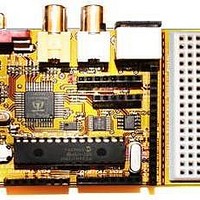
Step 4: Insert the A/V cable into the
the board and then insert them into your NTSC/Multi-System TV’s A/V port.
IMPORTANT!
We are going to assume you are running Windows XP or similar. Linux and Mac
systems are similar for this simple demo experiment. However, Linux and Mac detect
and install the FTDI USB drivers differently which we will cover in their respective setups
in the Appendices.
Figure 1.3 – The Console demo running – Crate-it!
ORANGE
(video) and WHITE (audio) port of the Chameleon PIC located top-right of
© 2009 NURVE NETWORKS LLC “Exploring the Chameleon PIC 16-Bit”
16
Related parts for Chameleon-PIC
Image
Part Number
Description
Manufacturer
Datasheet
Request
R

Part Number:
Description:
MCU, MPU & DSP Development Tools AVR8 VIDEO GAME DEV SYSTEM (SBC)
Manufacturer:
Nurve Networks

Part Number:
Description:
MCU, MPU & DSP Development Tools PIC24 VIDEO GAME DEV SYSTEM (SBC)
Manufacturer:
Nurve Networks

Part Number:
Description:
MCU, MPU & DSP Development Tools AVR8 & PROPELLER DEV SYSTEM (SBC)
Manufacturer:
Nurve Networks
Datasheet: