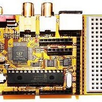
Chameleon-PIC Nurve Networks, Chameleon-PIC Datasheet - Page 48

Chameleon-PIC
Manufacturer Part Number
Chameleon-PIC
Description
MCU, MPU & DSP Development Tools PIC24 & PROPELLER DEV SYSTEM (SBC)
Manufacturer
Nurve Networks
Datasheet
1.CHAMELEON-PIC.pdf
(263 pages)
Specifications of Chameleon-PIC
Processor To Be Evaluated
PIC24
Data Bus Width
16 bit
Interface Type
USB, VGA, PS/2, I2C, ISP, SPI
Operating Supply Voltage
3.3 V, 5 V
Lead Free Status / RoHS Status
Lead free / RoHS Compliant
- Current page: 48 of 263
- Download datasheet (12Mb)
converted to the other before any common processing could be done. Interlaced scanning is where each picture, referred
to as a frame, is divided into two separate sub-pictures, referred to as fields.
Two fields make up a single frame. An interlaced picture is painted on the screen in two passes, by first scanning the
horizontal lines of the first field and then retracing to the top of the screen and then scanning the horizontal lines for the
second field in-between the first set. Field 1 consists of lines 1 through 262 1/2, and field 2 consists of lines 262 1/2
through 525. The interlaced principle is illustrated in Figure 11.3. Only a few lines at the top and the bottom of each field
are shown.
A progressive, or non-interlaced, picture is painted on the screen by scanning all of the horizontal lines of the picture in
one pass from the top to the bottom. This is illustrated in Figure 11.4.
NOTE
Most computer displays that output to TVs are progressive scans, that is, they draw a
single frame 60 times a second without interlacing. However, some computers and
game systems do put out interlaced video. The old Amiga computer was one such
example that had an interlaced video mode option to double the number of scanlines.
Figure 11.3 - Interlaced scanning system.
© 2009 NURVE NETWORKS LLC “Exploring the Chameleon PIC 16-Bit”
48
Related parts for Chameleon-PIC
Image
Part Number
Description
Manufacturer
Datasheet
Request
R

Part Number:
Description:
MCU, MPU & DSP Development Tools AVR8 VIDEO GAME DEV SYSTEM (SBC)
Manufacturer:
Nurve Networks

Part Number:
Description:
MCU, MPU & DSP Development Tools PIC24 VIDEO GAME DEV SYSTEM (SBC)
Manufacturer:
Nurve Networks

Part Number:
Description:
MCU, MPU & DSP Development Tools AVR8 & PROPELLER DEV SYSTEM (SBC)
Manufacturer:
Nurve Networks
Datasheet:


