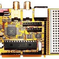
Chameleon-PIC Nurve Networks, Chameleon-PIC Datasheet - Page 47

Chameleon-PIC
Manufacturer Part Number
Chameleon-PIC
Description
MCU, MPU & DSP Development Tools PIC24 & PROPELLER DEV SYSTEM (SBC)
Manufacturer
Nurve Networks
Datasheet
1.CHAMELEON-PIC.pdf
(263 pages)
Specifications of Chameleon-PIC
Processor To Be Evaluated
PIC24
Data Bus Width
16 bit
Interface Type
USB, VGA, PS/2, I2C, ISP, SPI
Operating Supply Voltage
3.3 V, 5 V
Lead Free Status / RoHS Status
Lead free / RoHS Compliant
- Current page: 47 of 263
- Download datasheet (12Mb)
coverage of the Propeller’s graphics hardware (transcribed from the HYDRA book) in the Propeller Manual itself located
on the DVD here:
Now let’s discuss a little bit about NTSC video signal generation.
11.2 Introduction to NTSC Video
A video image is "drawn" on a television or computer display screen by sweeping an electrical signal (that controls a
beam of electrons that strike the screen’s phosphor surface) horizontally across the display one line at a time. The
amplitude of this signal versus time represents the instantaneous brightness at that physical point on the display. Figure
11.2 illustrates the signal amplitude relationship to the brightness on the display.
At the end of each line, there is a portion of the waveform (horizontal blanking interval) that instructs the scanning circuit in
the display to retrace to the left edge of the display and then start scanning the next line. Starting at the top, all of the lines
on the display are scanned in this way. One complete set of lines makes a frame. Once the first complete frame is
scanned, there is another portion of the waveform (vertical blanking interval, not shown) that tells the scanning circuit to
retrace to the top of the display and start scanning the next frame, or picture. This sequence is repeated at a fast enough
rate so that the displayed images are perceived to have continuous motion.
11.2.1 Interlaced versus Progressive Scans
These are two different types of scanning systems. They differ in the technique used to "render" the picture on the screen.
Television signals and compatible displays are typically interlaced, and computer signals and compatible displays are
typically progressive scan (non-interlaced). These two formats are incompatible with each other; one would need to be
DVD-ROM: \ cham_pic \docs \ propeller \ Propeller_Manual_WebPM-v1.1.pdf
NOTE
“IRE” is an arbitrary unit that relates to the voltage of the video signal, 100 IRE = 1.0V
these days; however, previously 140 IRE 1.0V. There is an EXACT spec for broadcast,
but many video generation hardware units assume a total of 1.0V for the total SYNC ->
WHITE video amplitude peak-peak voltage.
Figure 11.2 - Horizontal scan versus display brightness
© 2009 NURVE NETWORKS LLC “Exploring the Chameleon PIC 16-Bit”
47
Related parts for Chameleon-PIC
Image
Part Number
Description
Manufacturer
Datasheet
Request
R

Part Number:
Description:
MCU, MPU & DSP Development Tools AVR8 VIDEO GAME DEV SYSTEM (SBC)
Manufacturer:
Nurve Networks

Part Number:
Description:
MCU, MPU & DSP Development Tools PIC24 VIDEO GAME DEV SYSTEM (SBC)
Manufacturer:
Nurve Networks

Part Number:
Description:
MCU, MPU & DSP Development Tools AVR8 & PROPELLER DEV SYSTEM (SBC)
Manufacturer:
Nurve Networks
Datasheet:


