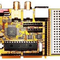
Chameleon-PIC Nurve Networks, Chameleon-PIC Datasheet - Page 51

Chameleon-PIC
Manufacturer Part Number
Chameleon-PIC
Description
MCU, MPU & DSP Development Tools PIC24 & PROPELLER DEV SYSTEM (SBC)
Manufacturer
Nurve Networks
Datasheet
1.CHAMELEON-PIC.pdf
(263 pages)
Specifications of Chameleon-PIC
Processor To Be Evaluated
PIC24
Data Bus Width
16 bit
Interface Type
USB, VGA, PS/2, I2C, ISP, SPI
Operating Supply Voltage
3.3 V, 5 V
Lead Free Status / RoHS Status
Lead free / RoHS Compliant
- Current page: 51 of 263
- Download datasheet (12Mb)
© 2009 NURVE NETWORKS LLC “Exploring the Chameleon PIC 16-Bit”
Figure 11.5 - NTSC composite video waveform.
This figure depicts the portion of the signal that represents one horizontal scan line. Each line is made up of the active
video portion and the horizontal blanking portion. The active video portion contains the picture brightness (luma) and color
(chroma) information. The brightness information is the instantaneous amplitude at any point in time. The unit of measure
for the amplitude is in terms of an IRE unit. IRE is an arbitrary unit where 140 IRE = 1Vp-p (or sometimes 1.4Vp-p). From
the figure, you can see that the voltage during the active video portion would yield a bright-white picture for this horizontal
scan line, whereas the horizontal blanking portion would be displayed as black and therefore not seen on the screen.
Please refer back to Figure 11.3..4 for a pictorial explanation. Some video systems (NTSC only) use something called
"setup," which places reference black a point equal to 7.5 IRE or about 54mV above the blanking level.
Figure 11.6 (a) - NTSC composite video waveform.
Figure 11.6 (a) depicts yet another timing drawing the NTSC video signal, this time, more formally labeled at the RS-170A
color standard created in the early 1950’s as the successor to the B/W only RS-170 standard created 1941.
51
Related parts for Chameleon-PIC
Image
Part Number
Description
Manufacturer
Datasheet
Request
R

Part Number:
Description:
MCU, MPU & DSP Development Tools AVR8 VIDEO GAME DEV SYSTEM (SBC)
Manufacturer:
Nurve Networks

Part Number:
Description:
MCU, MPU & DSP Development Tools PIC24 VIDEO GAME DEV SYSTEM (SBC)
Manufacturer:
Nurve Networks

Part Number:
Description:
MCU, MPU & DSP Development Tools AVR8 & PROPELLER DEV SYSTEM (SBC)
Manufacturer:
Nurve Networks
Datasheet:


