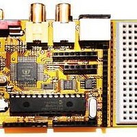
Chameleon-PIC Nurve Networks, Chameleon-PIC Datasheet - Page 106

Chameleon-PIC
Manufacturer Part Number
Chameleon-PIC
Description
MCU, MPU & DSP Development Tools PIC24 & PROPELLER DEV SYSTEM (SBC)
Manufacturer
Nurve Networks
Datasheet
1.CHAMELEON-PIC.pdf
(263 pages)
Specifications of Chameleon-PIC
Processor To Be Evaluated
PIC24
Data Bus Width
16 bit
Interface Type
USB, VGA, PS/2, I2C, ISP, SPI
Operating Supply Voltage
3.3 V, 5 V
Lead Free Status / RoHS Status
Lead free / RoHS Compliant
- Current page: 106 of 263
- Download datasheet (12Mb)
When you choose the PICkit 2 as the programmer for MPLAB a new toolbar appears on the right side of the MPLAB’s
existing toolbars. The new toolbar should look like that in Figure 15.45 (numbers are superimposed and NOT in MPLAB).
This toolbar is one method that we can use to control the PICkit 2 through MPLAB; the other is through the
<Programmer> menu that has been updated after selecting PICkit 2. Below is a description of the toolbar icons that are
numbered from left to right in Figure 15.45:
Now that the programmer is attached to the Chameleon PIC we can tell the PICkit 2 device programmer to flash the
binary file into the PIC24 processor. To do this press the far left toolbar button “Program the target device” (1) as shown
in Figure 15.45. This will begin loading the firmware into the Chameleon PIC and you may watch the progress through the
PICkit 2 tab on the output window. After it’s done programming the processor the PICkit 2 automatically verifies the
contents were written correctly. If all was well the output window will say “PICkit 2 Ready”.
1. Program the target device.
2. Read target device memories.
3. Read target EEDATA memory (not available with the PIC24HJ128GP502).
4. Verify the contents of the target device.
5. Erase the target device memories.
6. Verify the target memories are erased.
7. Bring target MCLR to VDD (remove device from reset so that it can operate normally).
8. Bring target MCLR to GND (place device in reset).
9. Re-establish PICkit 2 connection.
NOTE
NOTE
Only one programmer or debugger may be selected at a time. Once a programmer is
selected it will remove the previous programmer’s toolbar icons and replace them with its
own. MPLAB will also attempt to communicate with the project’s configured device through
the programming tool and verify that a device is attached. Diagnostic output can be viewed
in the output window under the programmer’s tabbed section.
If you are ever having problems connecting the PICkit 2 to the Chameleon PIC it may be a
number of reasons. First if you are attaching your PICkit 2 to a USB hub, and then your
computer, try removing the hub and connecting it directly to your computer. Next if MPLAB
recognizes the PICkit 2 but gives you a “device id error”; close down MPLAB, unplug the
PICkit 2 from the PC, and shut off the Chameleon PIC. Then turn on the Chameleon PIC, re-
insert the PICkit 2 into your PC, and start MPLAB. This will fix the problem 90% of the time.
If not, restart your computer and power cycle the Chameleon PIC.
Figure 15.44 – Selecting the PICkit 2 programmer.
Figure 15.45 – PICkit 2 programmer toolbar.
© 2009 NURVE NETWORKS LLC “Exploring the Chameleon PIC 16-Bit”
106
Related parts for Chameleon-PIC
Image
Part Number
Description
Manufacturer
Datasheet
Request
R

Part Number:
Description:
MCU, MPU & DSP Development Tools AVR8 VIDEO GAME DEV SYSTEM (SBC)
Manufacturer:
Nurve Networks

Part Number:
Description:
MCU, MPU & DSP Development Tools PIC24 VIDEO GAME DEV SYSTEM (SBC)
Manufacturer:
Nurve Networks

Part Number:
Description:
MCU, MPU & DSP Development Tools AVR8 & PROPELLER DEV SYSTEM (SBC)
Manufacturer:
Nurve Networks
Datasheet:


