Chameleon-PIC Nurve Networks, Chameleon-PIC Datasheet - Page 158
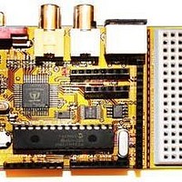
Chameleon-PIC
Manufacturer Part Number
Chameleon-PIC
Description
MCU, MPU & DSP Development Tools PIC24 & PROPELLER DEV SYSTEM (SBC)
Manufacturer
Nurve Networks
Datasheet
1.CHAMELEON-PIC.pdf
(263 pages)
Specifications of Chameleon-PIC
Processor To Be Evaluated
PIC24
Data Bus Width
16 bit
Interface Type
USB, VGA, PS/2, I2C, ISP, SPI
Operating Supply Voltage
3.3 V, 5 V
Lead Free Status / RoHS Status
Lead free / RoHS Compliant


19.1.1 Basic SPI Communications Steps
Figures 19.2(a) and (b) show the complete timing diagrams for all variants of clock polarity (CPOL) and clock phase
(CPHA). You must adhere to these timing constraints during communications. In most cases, you will use mode 0 since
it’s the default that most SPI devices boot with.
The good news is this is all taken care of by the PIC24, in fact, most PIC microcontrollers have complete SPI (and I
hardware built in that take care of all the details of both transmission and reception. The only thing we have to do as
programmers is set the hardware up, then send and receive bytes (and maybe handle an interrupt or two). Thus, working
with SPI in the PIC24 is very easy. Nonetheless, the library module we developed wraps the SPI hardware with a thin
layer of functions, so that you don’t have to deal with it all yourself. However, it’s good to understand the protocol if you
need to manually build a SPI interface with I/O pins. For example, maybe you need (4) SPI interfaces all at the same time
on the Chameleon’s expansion port, the only way to do this will be to do it manually with pin toggling.
Figure 19.3(a) – SPI timing diagrams for clock phase polarity (CPHA=0).
Figure 19.3(b) – SPI timing diagrams for clock phase polarity (CPHA=1).
© 2009 NURVE NETWORKS LLC “Exploring the Chameleon PIC 16-Bit”
2
C)
158
Related parts for Chameleon-PIC
Image
Part Number
Description
Manufacturer
Datasheet
Request
R

Part Number:
Description:
MCU, MPU & DSP Development Tools AVR8 VIDEO GAME DEV SYSTEM (SBC)
Manufacturer:
Nurve Networks

Part Number:
Description:
MCU, MPU & DSP Development Tools PIC24 VIDEO GAME DEV SYSTEM (SBC)
Manufacturer:
Nurve Networks

Part Number:
Description:
MCU, MPU & DSP Development Tools AVR8 & PROPELLER DEV SYSTEM (SBC)
Manufacturer:
Nurve Networks
Datasheet: