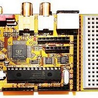
Chameleon-PIC Nurve Networks, Chameleon-PIC Datasheet - Page 144

Chameleon-PIC
Manufacturer Part Number
Chameleon-PIC
Description
MCU, MPU & DSP Development Tools PIC24 & PROPELLER DEV SYSTEM (SBC)
Manufacturer
Nurve Networks
Datasheet
1.CHAMELEON-PIC.pdf
(263 pages)
Specifications of Chameleon-PIC
Processor To Be Evaluated
PIC24
Data Bus Width
16 bit
Interface Type
USB, VGA, PS/2, I2C, ISP, SPI
Operating Supply Voltage
3.3 V, 5 V
Lead Free Status / RoHS Status
Lead free / RoHS Compliant
- Current page: 144 of 263
- Download datasheet (12Mb)
© 2009 NURVE NETWORKS LLC “Exploring the Chameleon PIC 16-Bit”
Figure 18.1 – The system architecture of the UART driver.
Hopefully, you have read thru the application notes and data sheet on the PIC UARTs. Nonetheless, serial
communications at the PC level is usually quite easy. The PC has an API, hardware, interrupts, and lots of sub-systems,
so that you are insulated from what’s really going on. This is not true with microcontrollers. The PIC24 series has
hardware UARTs to take the load off the bit banging, polling, and transmission and reception of actual bytes, but we still
need to write a lot of software on top of the hardware to develop an API that is useful.
There are lots of ways to approach this; for example, if you are happy with waiting for characters you could write a receive
function that simply waits for the reception buffer to get a character, this is slow though since you have to poll for it.
Secondly, you could do the same with your transmission software and write a loop that constantly writes bytes to the
transmit buffer while waiting for the bytes to transmit before writing another. These methods are fine, but I wanted to give
you a little bit more to work with as a starting point, so you can see how you might develop a more robust serial
communications system. Referring to Figure 18.1, this is the architecture of the UART module we have developed. The
UART driver API is an interrupt driven system with circular buffers on both the incoming and outgoing characters. The
system is easy to understand from a design perspective; interrupts are setup to fire when both a character has been
received and when a character has been transmitted. These interrupts both call “interrupt service routines” (ISRs) that
have been developed to support “circular buffers”. These circular buffers allow the calling functions to place characters
in the outgoing buffer and queued for transmission as well as for characters to fill up the receiving circular buffer until the
caller wants to read characters.
The idea of this being the functions that transmit and receive characters do not have to wait, they make two functions that
interrogate the circular buffers and either insert or remove characters. This way the system is responsive and only if the
buffers are overflowed is data lost. For example, say you want to transmit the string “Hello World!”. Normally, you would
have to transmit the “H”, then wait, “e”, then wait, etc. But, with interrupt driven architecture and the buffers, the string is
simply copied into the circular output buffer and the interrupt sends the string out for you.
The receiver is the same, you can interrogate the circular buffer anytime you wish. For example, say that you know the
transmitter on the other end is going to send a single string “The World is Fine.” back to you. This string fits into the
circular buffer, so you don’t have to interrogate the buffer immediately and worry about loss of data. You can finish you
activities, maybe a disk I/O or some rendering then at your leisure call the receive function which will check the buffer for
data and send it to you.
Referring to Figure 18.1 once again, you can see some of the details of the system. There are two functions similar to the
C putchar(…) and getchar(…) called UART_putchar(…) and UART_getchar(…) these functions directly access the
transmit and receive buffers for you. Thus, from a software perspective all the work of polling the transmission and
144
Related parts for Chameleon-PIC
Image
Part Number
Description
Manufacturer
Datasheet
Request
R

Part Number:
Description:
MCU, MPU & DSP Development Tools AVR8 VIDEO GAME DEV SYSTEM (SBC)
Manufacturer:
Nurve Networks

Part Number:
Description:
MCU, MPU & DSP Development Tools PIC24 VIDEO GAME DEV SYSTEM (SBC)
Manufacturer:
Nurve Networks

Part Number:
Description:
MCU, MPU & DSP Development Tools AVR8 & PROPELLER DEV SYSTEM (SBC)
Manufacturer:
Nurve Networks
Datasheet:


