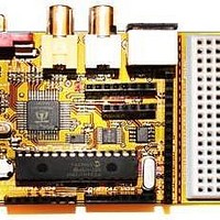
Chameleon-PIC Nurve Networks, Chameleon-PIC Datasheet - Page 46

Chameleon-PIC
Manufacturer Part Number
Chameleon-PIC
Description
MCU, MPU & DSP Development Tools PIC24 & PROPELLER DEV SYSTEM (SBC)
Manufacturer
Nurve Networks
Datasheet
1.CHAMELEON-PIC.pdf
(263 pages)
Specifications of Chameleon-PIC
Processor To Be Evaluated
PIC24
Data Bus Width
16 bit
Interface Type
USB, VGA, PS/2, I2C, ISP, SPI
Operating Supply Voltage
3.3 V, 5 V
Lead Free Status / RoHS Status
Lead free / RoHS Compliant
- Current page: 46 of 263
- Download datasheet (12Mb)
11.0 NTSC/PAL Composite Video Hardware
To begin with there are many online and written sources for NTSC, the primary online resource is located here:
At the end of the discussion on NTSC there is a list of other resources as well.
11.1 Video Hardware Interface
Referring to Figure 11.1, the composite video generation hardware consists nothing more than a crude 3-bit D/A converter
(summing circuit) along with a single signal for audio summed with the node as well. The real magic of the video
generation is up to the Propeller chip, it not only generates the luma (brightness), but the chroma (color) in the proper
format and timing for whatever the desired protocol is (NTSC or PAL).
The Propeller chip video hardware is designed to be interfaced to a simple 3-bit DAC with the resistance values chosen
and shown above in the figure. Table 11.1 shows the signal relationship to the Propeller I/O signals.
Prop Port Bit
P12
P13
P14
P15
There are 3-bits of D/A conversion for the overall composite video signal VIDEO_0-3 thus giving a total of 8 different
overall LUMA values; however, a number of them at the low scale of the range must be used to jump from “sync level”
0.0V to “black level” 0.25 - 0.3V. For example if the entire D/A range is 1.0V then 0.3 / 1.0 = 30%, 30% of 7 is 2, thus the
3-bit value of 0 is sync while the 4-bit value of 2 is black, leaving us with only the values 3-7 or 5 different intensity levels.
Additionally, since the chroma signal rides on top of the luma signal there is yet another constraint since the chroma need
to have a peak to peak of at least 2 units, this in fact, we can only drive the video signal to a value of 6, so the Propeller’s
chroma hardware can twiddle the luma +-1 to obtain the chroma. However, in fact most drivers simply use 0 as sync, 1 as
black, then values 1…6 as shades of gray. This gives us a total luma range of 6 values and still allows color to work which
the Propeller is designed to be able output 16 phase shifts of the color burst. This gives a total color/luma range of 16*6 =
96 colors without resorting to tricks. If you are really interested in how to write graphics drivers you should peruse the
source code of the various graphics drivers written by various authors for the Propeller. Additionally, the only reference
book that explains in detail how the graphics system works is “Game Programming for the Propeller Powered
HYDRA” which you can find on Amazon.com, Parallax.com, and XGameStation.com. There is also some minimal
http://www.ntsc-tv.com/
Chameleon Signal
VIDEO_0
VIDEO_1
VIDEO_2
AURAL_0
Figure 11.1 – The Chameleon PIC composite video hardware.
Bit 0 of the overall composite video signal (contains both LUMA and CHROMA).
Bit 1 of the overall composite video signal (contains both LUMA and CHROMA).
Bit 2 of the overall composite video signal (contains both LUMA and CHROMA).
Single “aural” audio bit used when transmitting broadcast video.
Description
Table 11.1 – The Video Hardware.
e Port Mapping Bits.
© 2009 NURVE NETWORKS LLC “Exploring the Chameleon PIC 16-Bit”
46
Related parts for Chameleon-PIC
Image
Part Number
Description
Manufacturer
Datasheet
Request
R

Part Number:
Description:
MCU, MPU & DSP Development Tools AVR8 VIDEO GAME DEV SYSTEM (SBC)
Manufacturer:
Nurve Networks

Part Number:
Description:
MCU, MPU & DSP Development Tools PIC24 VIDEO GAME DEV SYSTEM (SBC)
Manufacturer:
Nurve Networks

Part Number:
Description:
MCU, MPU & DSP Development Tools AVR8 & PROPELLER DEV SYSTEM (SBC)
Manufacturer:
Nurve Networks
Datasheet:


