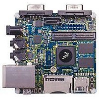
MCIMX53-START Freescale Semiconductor, MCIMX53-START Datasheet - Page 123

MCIMX53-START
Manufacturer Part Number
MCIMX53-START
Description
KIT DEVELOPMENT I.MX53
Manufacturer
Freescale Semiconductor
Series
i.MX53r
Type
MCUr
Datasheets
1.MCIMX53-START.pdf
(2 pages)
2.MCIMX53-START.pdf
(180 pages)
3.MCIMX53-START.pdf
(204 pages)
Specifications of MCIMX53-START
Contents
Board
Silicon Manufacturer
Freescale
Core Architecture
ARM
Core Sub-architecture
Cortex - A8
Silicon Core Number
I.MX5
Silicon Family Name
I.MX53
Peak Reflow Compatible (260 C)
Yes
Rohs Compliant
Yes
Leaded Process Compatible
Yes
Lead Free Status / RoHS Status
Lead free / RoHS Compliant
For Use With/related Products
i.MX53
Lead Free Status / Rohs Status
Supplier Unconfirmed
Available stocks
Company
Part Number
Manufacturer
Quantity
Price
- Current page: 123 of 204
- Download datasheet (2Mb)
4.7.13.1.1
The total phase jitter on the reference clock is specified at 3 ps RMS. There are numerous ways to measure
the reference clock jitter, one of which is as follows.
Using a high-speed sampling scope (20 GSamples/s), 1 million samples of the differential reference clock
are taken, and the zero-crossing times of each rising edge are calculated. From the zero-crossing data, an
average reference clock period is calculated. This average reference clock period is subtracted from each
sequential, instantaneous period to find the difference between each reference clock rising edge and the
ideal placement to produce the phase jitter sequence. The power spectral density (PSD) of the phase jitter
is calculated and integrated after being weighted with the transfer function shown in
root of the resultant integral is the RMS total phase jitter.
4.7.13.2 Transmitter and Receiver Characteristics
The SATA PHY meets or exceeds the electrical compliance requirements defined in the SATA
specification. The following subsections provide values obtained from a combination of simulations and
silicon characterization.
4.7.13.2.1
Table 75
Freescale Semiconductor
Transmit common mode voltage
Transmitter pre-emphasis accuracy (measured
change in de-emphasized bit)
provides specifications for SATA PHY transmitter characteristics.
Reference Clock Jitter Measurement
SATA PHY Transmitter Characteristics
The tables in the following sections indicate any exceptions to the SATA
specification or aspects of the SATA PHY that exceed the standard, as well
as provide information about parameters not defined in the standard.
Parameters
Figure 76. Weighting Function for RMS Phase Jitter Calculation
i.MX53xD Applications Processors for Consumer Products, Rev. 1
Table 75. SATA2 PHY Transmitter Characteristics
V
—
CTM
NOTE
Symbol
–0.5
Min
0.4
Typ
—
—
Electrical Characteristics
Figure
76. The square
Max
0.6
0.5
Unit
dB
V
123
Related parts for MCIMX53-START
Image
Part Number
Description
Manufacturer
Datasheet
Request
R
Part Number:
Description:
MCIMX-LVDS1
Manufacturer:
Freescale Semiconductor
Datasheet:
Part Number:
Description:
Manufacturer:
Freescale Semiconductor, Inc
Datasheet:
Part Number:
Description:
Manufacturer:
Freescale Semiconductor, Inc
Datasheet:
Part Number:
Description:
Manufacturer:
Freescale Semiconductor, Inc
Datasheet:
Part Number:
Description:
Manufacturer:
Freescale Semiconductor, Inc
Datasheet:
Part Number:
Description:
Manufacturer:
Freescale Semiconductor, Inc
Datasheet:
Part Number:
Description:
Manufacturer:
Freescale Semiconductor, Inc
Datasheet:
Part Number:
Description:
Manufacturer:
Freescale Semiconductor, Inc
Datasheet:
Part Number:
Description:
Manufacturer:
Freescale Semiconductor, Inc
Datasheet:
Part Number:
Description:
Manufacturer:
Freescale Semiconductor, Inc
Datasheet:
Part Number:
Description:
Manufacturer:
Freescale Semiconductor, Inc
Datasheet:
Part Number:
Description:
Manufacturer:
Freescale Semiconductor, Inc
Datasheet:
Part Number:
Description:
Manufacturer:
Freescale Semiconductor, Inc
Datasheet:
Part Number:
Description:
Manufacturer:
Freescale Semiconductor, Inc
Datasheet:
Part Number:
Description:
Manufacturer:
Freescale Semiconductor, Inc
Datasheet:


