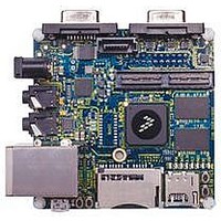
MCIMX53-START Freescale Semiconductor, MCIMX53-START Datasheet - Page 76

MCIMX53-START
Manufacturer Part Number
MCIMX53-START
Description
KIT DEVELOPMENT I.MX53
Manufacturer
Freescale Semiconductor
Series
i.MX53r
Type
MCUr
Datasheets
1.MCIMX53-START.pdf
(2 pages)
2.MCIMX53-START.pdf
(180 pages)
3.MCIMX53-START.pdf
(204 pages)
Specifications of MCIMX53-START
Contents
Board
Silicon Manufacturer
Freescale
Core Architecture
ARM
Core Sub-architecture
Cortex - A8
Silicon Core Number
I.MX5
Silicon Family Name
I.MX53
Peak Reflow Compatible (260 C)
Yes
Rohs Compliant
Yes
Leaded Process Compatible
Yes
Lead Free Status / RoHS Status
Lead free / RoHS Compliant
For Use With/related Products
i.MX53
Lead Free Status / Rohs Status
Supplier Unconfirmed
Available stocks
Company
Part Number
Manufacturer
Quantity
Price
- Current page: 76 of 204
- Download datasheet (2Mb)
Electrical Characteristics
4.7.5.3
Table 50
input timings listed in
1
2
4.7.5.4
Table 51
timings listed in
with the IEEE 802.3 MII specification. However, the FEC can function correctly with a maximum MDC
frequency of 15 MHz.
76
M10 FEC_MDC falling edge to FEC_MDIO output invalid (minimum propagation delay)
M11 FEC_MDC falling edge to FEC_MDIO output valid (max propagation delay)
M12 FEC_MDIO (input) to FEC_MDC rising edge setup
.
.
Test conditions: 25pF on each output signal.
FEC_COL has the same timing in 10 Mbit 7-wire interface mode.
ID
Num
M9
2
FEC_TXD[3:0] (outputs)
FEC_TX_CLK (input)
lists MII serial management channel timings.
lists MII asynchronous inputs signal timing information.
FEC_CRS, FEC_COL
MII Async Inputs Signal Timing (FEC_CRS and FEC_COL)
MII Serial Management Channel Timing (FEC_MDIO and FEC_MDC)
FEC_TX_EN
FEC_TX_ER
FEC_CRS to FEC_COL minimum pulse width
Table
Table
51. The MDC frequency should be equal to or less than 2.5 MHz to be compliant
i.MX53xD Applications Processors for Consumer Products, Rev. 1
Characteristic
50.
Figure 37. MII Transmit Signal Timing Diagram
Figure 38. MII Async Inputs Timing Diagram
Table 50. MII Async Inputs Signal Timing
Table 51. MII Transmit Signal Timing
Characteristics
1
M5
1
M6
M7
Figure 39
M9
Min
1.5
shows MII serial management channel
Figure 38
M8
Max
—
shows MII asynchronous
Min Max
18
—
0
FEC_TX_CLK period
Freescale Semiconductor
—
—
5
Unit
Unit
ns
ns
ns
Related parts for MCIMX53-START
Image
Part Number
Description
Manufacturer
Datasheet
Request
R
Part Number:
Description:
MCIMX-LVDS1
Manufacturer:
Freescale Semiconductor
Datasheet:
Part Number:
Description:
Manufacturer:
Freescale Semiconductor, Inc
Datasheet:
Part Number:
Description:
Manufacturer:
Freescale Semiconductor, Inc
Datasheet:
Part Number:
Description:
Manufacturer:
Freescale Semiconductor, Inc
Datasheet:
Part Number:
Description:
Manufacturer:
Freescale Semiconductor, Inc
Datasheet:
Part Number:
Description:
Manufacturer:
Freescale Semiconductor, Inc
Datasheet:
Part Number:
Description:
Manufacturer:
Freescale Semiconductor, Inc
Datasheet:
Part Number:
Description:
Manufacturer:
Freescale Semiconductor, Inc
Datasheet:
Part Number:
Description:
Manufacturer:
Freescale Semiconductor, Inc
Datasheet:
Part Number:
Description:
Manufacturer:
Freescale Semiconductor, Inc
Datasheet:
Part Number:
Description:
Manufacturer:
Freescale Semiconductor, Inc
Datasheet:
Part Number:
Description:
Manufacturer:
Freescale Semiconductor, Inc
Datasheet:
Part Number:
Description:
Manufacturer:
Freescale Semiconductor, Inc
Datasheet:
Part Number:
Description:
Manufacturer:
Freescale Semiconductor, Inc
Datasheet:
Part Number:
Description:
Manufacturer:
Freescale Semiconductor, Inc
Datasheet:


