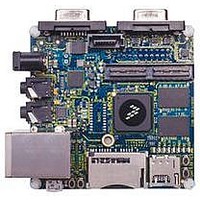
MCIMX53-START Freescale Semiconductor, MCIMX53-START Datasheet - Page 150

MCIMX53-START
Manufacturer Part Number
MCIMX53-START
Description
KIT DEVELOPMENT I.MX53
Manufacturer
Freescale Semiconductor
Series
i.MX53r
Type
MCUr
Datasheets
1.MCIMX53-START.pdf
(2 pages)
2.MCIMX53-START.pdf
(180 pages)
3.MCIMX53-START.pdf
(204 pages)
Specifications of MCIMX53-START
Contents
Board
Silicon Manufacturer
Freescale
Core Architecture
ARM
Core Sub-architecture
Cortex - A8
Silicon Core Number
I.MX5
Silicon Family Name
I.MX53
Peak Reflow Compatible (260 C)
Yes
Rohs Compliant
Yes
Leaded Process Compatible
Yes
Lead Free Status / RoHS Status
Lead free / RoHS Compliant
For Use With/related Products
i.MX53
Lead Free Status / Rohs Status
Supplier Unconfirmed
Available stocks
Company
Part Number
Manufacturer
Quantity
Price
- Current page: 150 of 204
- Download datasheet (2Mb)
Boot Mode Configuration
4.9
The PLL supplies VDD_DIG_PLL and VDD_ANA_PLL can be powered ON from internal LDO voltage
regulator (default case). In this case VDD_REG is used as internal regulator’s power source. The
regulator’s output can be used as a supply for other domains such as VDDA and VDDAL1.
Table 106
5
This section provides information on boot mode configuration pins allocation and boot devices interfaces
allocation.
5.1
Table 107
sampled at reset and can be used to override fuse values, depending on the value of BT_FUSE_SEL fuse.
The boot option pins are in effect when BT_FUSE_SEL fuse is ‘0’ (cleared, which is the case for an
unblown fuse). For detailed boot mode options configured by the boot mode pins, please refer to the
i.MX53xD Fuse Map document and Boot Chapter in i.MX53xD Reference Manual.
150
1
2
3
VDD_DIG_PLL functional Voltage
Range
VDD_ANA_PLL functional Voltage
Range
VDD_DIG_PLL and VDD_ANA_PLL
accuracy
VDD_DIG_PLL power-supply rejection
ratio
VDD_ANA_PLL power-supply rejection
ratio
Output current
for proper PLL operation.
The gain or attenuation from the input supply variation to the output of the LDO (by design).
The limitation is for sum of the VDD_DIG_PLL and VDD_ANA_PLL current.
BOOT_MODE[1]
BOOT_MODE[0]
VDD_DIG_PLL and VDD_ANA_PLL voltages are programmable, but should not be set outside the target functional range
2
2
1
1
Boot Mode Configuration
Pin
Integrated LDO Voltage Regulators Parameters
Boot Mode Configuration Pins
provides boot options, functionality, fuse values, and associated pins. Several input pins are also
shows the VDD_DIG_PLL and VDD_ANA_PLL Integrated Voltage Regulators Parameters.
3
Parameter
Direction at
Table 106. LDO Voltage Regulators Electrical Specifications
i.MX53xD Applications Processors for Consumer Products, Rev. 1
Reset
Input
Input
Table 107. Fuses and Associated Pins Used for Boot
V
I
I
V
VID_DIG_PLL
VDD_ANA_PLL
VDD_ANA_PLL
VID_DIG_PLL
Symbol
—
—
—
E-Fuse Name
+
N/A
1.15
Min
1.7
—
—
—
—
Typ
–18
–15
1.2
1.8
—
—
Boot Mode selection
Details
Freescale Semiconductor
Max
1.95
+/–3
125
1.3
—
—
Units
mA
dB
dB
%
V
V
Related parts for MCIMX53-START
Image
Part Number
Description
Manufacturer
Datasheet
Request
R
Part Number:
Description:
MCIMX-LVDS1
Manufacturer:
Freescale Semiconductor
Datasheet:
Part Number:
Description:
Manufacturer:
Freescale Semiconductor, Inc
Datasheet:
Part Number:
Description:
Manufacturer:
Freescale Semiconductor, Inc
Datasheet:
Part Number:
Description:
Manufacturer:
Freescale Semiconductor, Inc
Datasheet:
Part Number:
Description:
Manufacturer:
Freescale Semiconductor, Inc
Datasheet:
Part Number:
Description:
Manufacturer:
Freescale Semiconductor, Inc
Datasheet:
Part Number:
Description:
Manufacturer:
Freescale Semiconductor, Inc
Datasheet:
Part Number:
Description:
Manufacturer:
Freescale Semiconductor, Inc
Datasheet:
Part Number:
Description:
Manufacturer:
Freescale Semiconductor, Inc
Datasheet:
Part Number:
Description:
Manufacturer:
Freescale Semiconductor, Inc
Datasheet:
Part Number:
Description:
Manufacturer:
Freescale Semiconductor, Inc
Datasheet:
Part Number:
Description:
Manufacturer:
Freescale Semiconductor, Inc
Datasheet:
Part Number:
Description:
Manufacturer:
Freescale Semiconductor, Inc
Datasheet:
Part Number:
Description:
Manufacturer:
Freescale Semiconductor, Inc
Datasheet:
Part Number:
Description:
Manufacturer:
Freescale Semiconductor, Inc
Datasheet:


