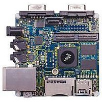
MCIMX53-START Freescale Semiconductor, MCIMX53-START Datasheet - Page 18

MCIMX53-START
Manufacturer Part Number
MCIMX53-START
Description
KIT DEVELOPMENT I.MX53
Manufacturer
Freescale Semiconductor
Series
i.MX53r
Type
MCUr
Datasheets
1.MCIMX53-START.pdf
(2 pages)
2.MCIMX53-START.pdf
(180 pages)
3.MCIMX53-START.pdf
(204 pages)
Specifications of MCIMX53-START
Contents
Board
Silicon Manufacturer
Freescale
Core Architecture
ARM
Core Sub-architecture
Cortex - A8
Silicon Core Number
I.MX5
Silicon Family Name
I.MX53
Peak Reflow Compatible (260 C)
Yes
Rohs Compliant
Yes
Leaded Process Compatible
Yes
Lead Free Status / RoHS Status
Lead free / RoHS Compliant
For Use With/related Products
i.MX53
Lead Free Status / Rohs Status
Supplier Unconfirmed
Available stocks
Company
Part Number
Manufacturer
Quantity
Price
- Current page: 18 of 204
- Download datasheet (2Mb)
Electrical Characteristics
4.1.2
Table 5
18
1
2
1
2
3
Peripheral Core Supply Voltage
ARM Core Supply Voltage
Supply Voltage UHVIO
Supply Voltage for non UHVIO
USB VBUS
Input voltage on USB_OTG_DP, USB_OTG_DN,
USB_H1_DP, USB_H1_DN pins
Input/Output Voltage Range
ESD Damage Immunity:
Storage Temperature Range
Junction to Ambient (natural convection)
Junction to Ambient (natural convection)
Junction to Ambient (@200 ft/min)
Junction to Ambient (@200 ft/min)
Junction to Board
Junction to Case
Junction to Package Top (natural convection)
USB_DN and USB_DP can tolerate 5 V for up to 24 hours.
The term OVDD in this section refers to the associated supply rail of an input or output. The association is described in
Table 110 on page
Junction temperature is a function of die size, on-chip power dissipation, package thermal resistance, mounting site (board)
temperature, ambient temperature, air flow, power dissipation of other components on the board, and board thermal
resistance.
Per JEDEC JESD51-2 with the single layer board horizontal. Board meets JESD51-9 specification.
Per JEDEC JESD51-6 with the board horizontal.
provides the package thermal resistance data.
Thermal Resistance
Parameter Description
5
4
157. The maximum range can be superseded by the DC tables.
Charge Device Model (CDM)
Human Body Model (HBM)
Rating
i.MX53xD Applications Processors for Consumer Products, Rev. 1
1, 3
1, 3
Table 5. Package Thermal Resistance Data
1, 2
1, 2, 3
Table 4. Absolute Maximum Ratings
6
Supplies denoted as I/O Supply
Supplies denoted as I/O Supply
Single layer board
Single layer board
USB_DP/USB_DN
Four layer board
Four layer board
T
Board
Symbol
VDDGP
(2s2p)
(2s2p)
V
STORAGE
VBUS
(1s)
(1s)
VCC
in
V
—
—
—
/V
esd
out
Symbol
R
R
R
R
R
R
Ψ
θJMA
θJMA
θJC
θJA
θJA
θJB
JT
–0.3
–0.3
–0.5
–0.5
–0.3
–0.5
Min
–40
—
—
—
Value
Freescale Semiconductor
OVDD +0.3
28
16
21
13
6
4
4
3.63
2000
Max
1.35
1.35
5.25
500
150
3.6
3.3
1
2
°C/W
°C/W
°C/W
°C/W
°C/W
°C/W
°C/W
Unit
Unit
o
V
V
V
V
V
V
V
V
C
Related parts for MCIMX53-START
Image
Part Number
Description
Manufacturer
Datasheet
Request
R
Part Number:
Description:
MCIMX-LVDS1
Manufacturer:
Freescale Semiconductor
Datasheet:
Part Number:
Description:
Manufacturer:
Freescale Semiconductor, Inc
Datasheet:
Part Number:
Description:
Manufacturer:
Freescale Semiconductor, Inc
Datasheet:
Part Number:
Description:
Manufacturer:
Freescale Semiconductor, Inc
Datasheet:
Part Number:
Description:
Manufacturer:
Freescale Semiconductor, Inc
Datasheet:
Part Number:
Description:
Manufacturer:
Freescale Semiconductor, Inc
Datasheet:
Part Number:
Description:
Manufacturer:
Freescale Semiconductor, Inc
Datasheet:
Part Number:
Description:
Manufacturer:
Freescale Semiconductor, Inc
Datasheet:
Part Number:
Description:
Manufacturer:
Freescale Semiconductor, Inc
Datasheet:
Part Number:
Description:
Manufacturer:
Freescale Semiconductor, Inc
Datasheet:
Part Number:
Description:
Manufacturer:
Freescale Semiconductor, Inc
Datasheet:
Part Number:
Description:
Manufacturer:
Freescale Semiconductor, Inc
Datasheet:
Part Number:
Description:
Manufacturer:
Freescale Semiconductor, Inc
Datasheet:
Part Number:
Description:
Manufacturer:
Freescale Semiconductor, Inc
Datasheet:
Part Number:
Description:
Manufacturer:
Freescale Semiconductor, Inc
Datasheet:


