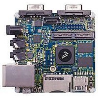
MCIMX53-START Freescale Semiconductor, MCIMX53-START Datasheet - Page 69

MCIMX53-START
Manufacturer Part Number
MCIMX53-START
Description
KIT DEVELOPMENT I.MX53
Manufacturer
Freescale Semiconductor
Series
i.MX53r
Type
MCUr
Datasheets
1.MCIMX53-START.pdf
(2 pages)
2.MCIMX53-START.pdf
(180 pages)
3.MCIMX53-START.pdf
(204 pages)
Specifications of MCIMX53-START
Contents
Board
Silicon Manufacturer
Freescale
Core Architecture
ARM
Core Sub-architecture
Cortex - A8
Silicon Core Number
I.MX5
Silicon Family Name
I.MX53
Peak Reflow Compatible (260 C)
Yes
Rohs Compliant
Yes
Leaded Process Compatible
Yes
Lead Free Status / RoHS Status
Lead free / RoHS Compliant
For Use With/related Products
i.MX53
Lead Free Status / Rohs Status
Supplier Unconfirmed
Available stocks
Company
Part Number
Manufacturer
Quantity
Price
- Current page: 69 of 204
- Download datasheet (2Mb)
1
2
3
4
5
6
7
Freescale Semiconductor
No.
82
83
84
86
89
90
91
95
96
97
87
VCORE_VDD= 1.00 +- 0.10V
i ck = internal clock
x ck = external clock
i ck a = internal clock, asynchronous mode
(asynchronous implies that SCKT and SCKR are two different clocks)
i ck s = internal clock, synchronous mode
(synchronous implies that SCKT and SCKR are the same clock)
bl = bit length
wl = word length
wr = word length relative
SCKT(SCKT pin) = transmit clock
SCKR(SCKR pin) = receive clock
FST(FST pin) = transmit frame sync
FSR(FSR pin) = receive frame sync
HCKT(HCKT pin) = transmit high frequency clock
HCKR(HCKR pin) = receive high frequency clock
For the internal clock, the external clock cycle is defined by Icyc and the ESAI control register.
The word-relative frame sync signal waveform relative to the clock operates in the same manner as the bit-length frame sync
signal waveform, but it spreads from one serial clock before the first bit clock (like the bit length frame sync signal), until the
second-to-last bit clock of the first word in the frame.
Periodically sampled and not 100% tested.
Tj = -40C to 125C
CL=50pF
SCKT rising edge to FST out (wl) high
SCKT rising edge to FST out (wl) low
SCKT rising edge to data out enable from high
impedance
SCKT rising edge to data out valid
SCKT rising edge to data out high impedance
FST input (bl, wr) setup time before SCKT falling edge
FST input (wl) setup time before SCKT falling edge
FST input hold time after SCKT falling edge
HCKR/HCKT clock cycle
HCKT input rising edge to SCKT output
HCKR input rising edge to SCKR output
Table 45. Enhanced Serial Audio Interface (ESAI) Timing (continued)
Characteristics
i.MX53xD Applications Processors for Consumer Products, Rev. 1
1
’
2,3
77
6
Symbol
—
—
—
—
—
—
—
—
—
—
—
—
—
—
—
—
—
—
—
Expression
2 x T
—
—
—
—
—
—
—
—
—
—
—
—
—
—
—
—
—
—
C
3
18.0
18.0
Min
2.0
2.0
4.0
5.0
15
—
—
—
—
—
—
—
—
—
—
—
—
Electrical Characteristics
Max
19.0
20.0
10.0
22.0
17.0
18.0
13.0
21.0
16.0
18.0
18.0
9.0
—
—
—
—
—
—
—
Condition
x ck
x ck
x ck
x ck
x ck
x ck
x ck
x ck
i ck
i ck
i ck
i ck
i ck
i ck
i ck
i ck
—
—
—
4
Unit
ns
ns
ns
ns
ns
ns
ns
ns
ns
ns
ns
69
Related parts for MCIMX53-START
Image
Part Number
Description
Manufacturer
Datasheet
Request
R
Part Number:
Description:
MCIMX-LVDS1
Manufacturer:
Freescale Semiconductor
Datasheet:
Part Number:
Description:
Manufacturer:
Freescale Semiconductor, Inc
Datasheet:
Part Number:
Description:
Manufacturer:
Freescale Semiconductor, Inc
Datasheet:
Part Number:
Description:
Manufacturer:
Freescale Semiconductor, Inc
Datasheet:
Part Number:
Description:
Manufacturer:
Freescale Semiconductor, Inc
Datasheet:
Part Number:
Description:
Manufacturer:
Freescale Semiconductor, Inc
Datasheet:
Part Number:
Description:
Manufacturer:
Freescale Semiconductor, Inc
Datasheet:
Part Number:
Description:
Manufacturer:
Freescale Semiconductor, Inc
Datasheet:
Part Number:
Description:
Manufacturer:
Freescale Semiconductor, Inc
Datasheet:
Part Number:
Description:
Manufacturer:
Freescale Semiconductor, Inc
Datasheet:
Part Number:
Description:
Manufacturer:
Freescale Semiconductor, Inc
Datasheet:
Part Number:
Description:
Manufacturer:
Freescale Semiconductor, Inc
Datasheet:
Part Number:
Description:
Manufacturer:
Freescale Semiconductor, Inc
Datasheet:
Part Number:
Description:
Manufacturer:
Freescale Semiconductor, Inc
Datasheet:
Part Number:
Description:
Manufacturer:
Freescale Semiconductor, Inc
Datasheet:


