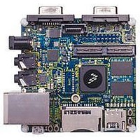
MCIMX53-START Freescale Semiconductor, MCIMX53-START Datasheet - Page 151

MCIMX53-START
Manufacturer Part Number
MCIMX53-START
Description
KIT DEVELOPMENT I.MX53
Manufacturer
Freescale Semiconductor
Series
i.MX53r
Type
MCUr
Datasheets
1.MCIMX53-START.pdf
(2 pages)
2.MCIMX53-START.pdf
(180 pages)
3.MCIMX53-START.pdf
(204 pages)
Specifications of MCIMX53-START
Contents
Board
Silicon Manufacturer
Freescale
Core Architecture
ARM
Core Sub-architecture
Cortex - A8
Silicon Core Number
I.MX5
Silicon Family Name
I.MX53
Peak Reflow Compatible (260 C)
Yes
Rohs Compliant
Yes
Leaded Process Compatible
Yes
Lead Free Status / RoHS Status
Lead free / RoHS Compliant
For Use With/related Products
i.MX53
Lead Free Status / Rohs Status
Supplier Unconfirmed
Available stocks
Company
Part Number
Manufacturer
Quantity
Price
- Current page: 151 of 204
- Download datasheet (2Mb)
5.2
Table 108
mode configuration. The table also describes the interface’s specific modes and IOMUXC allocation,
which are configured during boot when appropriate.
Freescale Semiconductor
Interface
SPI
SPI
SPI
EIM_DA10
EIM_LBA
EIM_EB0
EIM_EB1
EIM_DA0
EIM_DA1
EIM_DA2
EIM_DA3
EIM_DA4
EIM_DA5
EIM_DA6
EIM_DA7
EIM_DA8
EIM_DA9
EIM_A22
EIM_A21
EIM_A20
EIM_A19
EIM_A18
EIM_A17
EIM_A16
Pin
Boot Devices Interfaces Allocation
lists the interfaces that can be used by the boot process in accordance with the specific boot
IP Instance
ECSPI-1
ECSPI-2
CSPI
Direction at
i.MX53xD Applications Processors for Consumer Products, Rev. 1
Reset
Input
Input
Input
Input
Input
Input
Input
Input
Input
Input
Input
Input
Input
Input
Input
Input
Input
Input
Input
Input
Input
EIM_A25, EIM_D21, EIM_D22, EIM_D28
EIM_D[19:16]
CSI_DAT[10:8], EIM_LBA
Table 107. Fuses and Associated Pins Used for Boot
Table 108. Interfaces Allocation During Boot
Allocated Pads During Boot
BOOT_CFG1[7]/Test Mode Selection
BOOT_CFG1[6]/Test Mode Selection
BOOT_CFG1[5]/Test Mode Selection
BOOT_CFG1[4]
BOOT_CFG1[3]
BOOT_CFG1[2]
BOOT_CFG1[1]
BOOT_CFG1[0]
BOOT_CFG2[7]
BOOT_CFG2[6]
BOOT_CFG2[5]
BOOT_CFG2[4]
BOOT_CFG2[3]
BOOT_CFG2[2]
BOOT_CFG3[7]
BOOT_CFG3[6]
BOOT_CFG3[5]
BOOT_CFG3[4]
BOOT_CFG3[3]
BOOT_CFG3[2]
BOOT_CFG3[1]
E-Fuse Name
during product development. In production,
the boot configuration can be controlled by
lines that control the boot up configuration
Input at Power Up. These are special I/O
Boot Options, Pin value overrides fuse
Signal Configuration as Fuse Override
Only SS1 is supported
Only SS1 is supported
Only SS1 is supported
settings for BT_FUSE_SEL = ‘0’.
Boot Mode Configuration
Details
Comment
fuses.
151
Related parts for MCIMX53-START
Image
Part Number
Description
Manufacturer
Datasheet
Request
R
Part Number:
Description:
MCIMX-LVDS1
Manufacturer:
Freescale Semiconductor
Datasheet:
Part Number:
Description:
Manufacturer:
Freescale Semiconductor, Inc
Datasheet:
Part Number:
Description:
Manufacturer:
Freescale Semiconductor, Inc
Datasheet:
Part Number:
Description:
Manufacturer:
Freescale Semiconductor, Inc
Datasheet:
Part Number:
Description:
Manufacturer:
Freescale Semiconductor, Inc
Datasheet:
Part Number:
Description:
Manufacturer:
Freescale Semiconductor, Inc
Datasheet:
Part Number:
Description:
Manufacturer:
Freescale Semiconductor, Inc
Datasheet:
Part Number:
Description:
Manufacturer:
Freescale Semiconductor, Inc
Datasheet:
Part Number:
Description:
Manufacturer:
Freescale Semiconductor, Inc
Datasheet:
Part Number:
Description:
Manufacturer:
Freescale Semiconductor, Inc
Datasheet:
Part Number:
Description:
Manufacturer:
Freescale Semiconductor, Inc
Datasheet:
Part Number:
Description:
Manufacturer:
Freescale Semiconductor, Inc
Datasheet:
Part Number:
Description:
Manufacturer:
Freescale Semiconductor, Inc
Datasheet:
Part Number:
Description:
Manufacturer:
Freescale Semiconductor, Inc
Datasheet:
Part Number:
Description:
Manufacturer:
Freescale Semiconductor, Inc
Datasheet:


