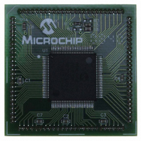
MA330013 Microchip Technology, MA330013 Datasheet - Page 135

MA330013
Manufacturer Part Number
MA330013
Description
MODULE PLUG-IN DSPIC33 100TQFP
Manufacturer
Microchip Technology
Specifications of MA330013
Accessory Type
Plug-In Module (PIM) - dsPIC33FJ256MC710
Tool / Board Applications
General Purpose MCU, MPU, DSP, DSC
Mcu Supported Families
DsPIC33
Silicon Manufacturer
Microchip
Core Architecture
DsPIC
Core Sub-architecture
DsPIC33
Silicon Core Number
DsPIC33F
Silicon Family Name
DsPIC33FJxxMCxxx
Rohs Compliant
Yes
For Use With
DM330023 - BOARD DEV DSPICDEM MCHV
Lead Free Status / RoHS Status
Not applicable / Not applicable
For Use With/related Products
Explorer 16 (DM240001 or DM240002)
Lead Free Status / RoHS Status
Lead free / RoHS Compliant, Not applicable / Not applicable
- Current page: 135 of 370
- Download datasheet (6Mb)
6.4
6.4.1
To configure an interrupt source:
1.
2.
3.
4.
6.4.2
The method that is used to declare an ISR and initialize
the IVT with the correct vector address will depend on
the programming language (i.e., C or assembler) and
the language development toolsuite that is used to
develop the application. In general, the user must clear
the interrupt flag in the appropriate IFSx register for the
source of interrupt that the ISR handles. Otherwise, the
ISR will be re-entered immediately after exiting the
routine. If the ISR is coded in assembly language, it
must be terminated using a RETFIE instruction to
unstack the saved PC value, SRL value and old CPU
priority level.
© 2007 Microchip Technology Inc.
Note:
Set the NSTDIS bit (INTCON1<15>) if nested
interrupts are not desired.
Select the user-assigned priority level for the
interrupt source by writing the control bits in the
appropriate IPCx register. The priority level will
depend on the specific application and type of
interrupt source. If multiple priority levels are not
desired, the IPCx register control bits for all
enabled interrupt sources may be programmed
to the same non-zero value.
Clear the interrupt flag status bit associated with
the peripheral in the associated IFSx register.
Enable the interrupt source by setting the inter-
rupt enable control bit associated with the
source in the appropriate IECx register.
Interrupt Setup Procedures
INITIALIZATION
INTERRUPT SERVICE ROUTINE
At a device Reset, the IPCx registers are
initialized, such that all user interrupt
sources are assigned to priority level 4.
Preliminary
6.4.3
A Trap Service Routine (TSR) is coded like an ISR,
except that the appropriate trap status flag in the
INTCON1 register must be cleared to avoid re-entry
into the TSR.
6.4.4
All user interrupts can be disabled using the following
procedure:
1.
2.
To enable user interrupts, the POP instruction may be
used to restore the previous SR value.
Note that only user interrupts with a priority level of 7 or
less can be disabled. Trap sources (level 8-level 15)
cannot be disabled.
The DISI instruction provides a convenient way to dis-
able interrupts of priority levels 1-6 for a fixed period of
time. Level 7 interrupt sources are not disabled by the
DISI instruction.
Push the current SR value onto the software
stack using the PUSH instruction.
Force the CPU to priority level 7 by inclusive
ORing the value OEh with SRL.
TRAP SERVICE ROUTINE
INTERRUPT DISABLE
dsPIC33F
DS70165E-page 133
Related parts for MA330013
Image
Part Number
Description
Manufacturer
Datasheet
Request
R

Part Number:
Description:
Manufacturer:
Microchip Technology Inc.
Datasheet:

Part Number:
Description:
Manufacturer:
Microchip Technology Inc.
Datasheet:

Part Number:
Description:
Manufacturer:
Microchip Technology Inc.
Datasheet:

Part Number:
Description:
Manufacturer:
Microchip Technology Inc.
Datasheet:

Part Number:
Description:
Manufacturer:
Microchip Technology Inc.
Datasheet:

Part Number:
Description:
Manufacturer:
Microchip Technology Inc.
Datasheet:

Part Number:
Description:
Manufacturer:
Microchip Technology Inc.
Datasheet:

Part Number:
Description:
Manufacturer:
Microchip Technology Inc.
Datasheet:


