C8051F320DK Silicon Laboratories Inc, C8051F320DK Datasheet - Page 162
C8051F320DK
Manufacturer Part Number
C8051F320DK
Description
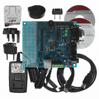
DEV KIT FOR C8051F320/F321
Manufacturer
Silicon Laboratories Inc
Type
MCUr
Specifications of C8051F320DK
Contents
Evaluation Board, Power Supply, USB Cables, Adapter and Documentation
Processor To Be Evaluated
C8051F320/F321
Interface Type
USB
Silicon Manufacturer
Silicon Labs
Core Architecture
8051
Silicon Core Number
C8051F320
Silicon Family Name
C8051F32x
Lead Free Status / RoHS Status
Contains lead / RoHS non-compliant
For Use With/related Products
Silicon Laboratories C8051F320, C8051F321
Lead Free Status / Rohs Status
Lead free / RoHS Compliant
Other names
336-1260
Available stocks
Company
Part Number
Manufacturer
Quantity
Price
Company:

Part Number:
C8051F320DK
Manufacturer:
SiliconL
Quantity:
4


C8051F320/1
A Bulk or Interrupt pipe can be shut down (or Halted) by writing ‘1’ to the SDSTL bit (EINCSRL.4). While
SDSTL = ‘1’, hardware will respond to all IN requests with a STALL condition. Each time hardware gener-
ates a STALL condition, an interrupt will be generated and the STSTL bit (EINCSRL.5) set to ‘1’. The
STSTL bit must be reset to ‘0’ by firmware.
Hardware will automatically reset INPRDY to ‘0’ when a packet slot is open in the endpoint FIFO. Note that
if double buffering is enabled for the target endpoint, it is possible for firmware to load two packets into the
IN FIFO at a time. In this case, hardware will reset INPRDY to ‘0’ immediately after firmware loads the first
packet into the FIFO and sets INPRDY to ‘1’. An interrupt will not be generated in this case; an interrupt will
only be generated when a data packet is transmitted.
When firmware writes ‘1’ to the FCDT bit (EINCSRH.3), the data toggle for each IN packet will be toggled
continuously, regardless of the handshake received from the host. This feature is typically used by Inter-
rupt endpoints functioning as rate feedback communication for Isochronous endpoints. When FCDT = ‘0’,
the data toggle bit will only be toggled when an ACK is sent from the host in response to an IN packet.
15.12.2.Endpoints1-3 IN Isochronous Mode
When the ISO bit (EINCSRH.6) is set to ‘1’, the target endpoint operates in Isochronous (ISO) mode. Once
an endpoint has been configured for ISO IN mode, the host will send one IN token (data request) per
frame; the location of data within each frame may vary. Because of this, it is recommended that double
buffering be enabled for ISO IN endpoints.
Hardware will automatically reset INPRDY (EINCSRL.0) to ‘0’ when a packet slot is open in the endpoint
FIFO. Note that if double buffering is enabled for the target endpoint, it is possible for firmware to load two
packets into the IN FIFO at a time. In this case, hardware will reset INPRDY to ‘0’ immediately after firm-
ware loads the first packet into the FIFO and sets INPRDY to ‘1’. An interrupt will not be generated in this
case; an interrupt will only be generated when a data packet is transmitted.
If there is not a data packet ready in the endpoint FIFO when USB0 receives an IN token from the host,
USB0 will transmit a zero-length data packet and set the UNDRUN bit (EINCSRL.2) to ‘1’.
The ISO Update feature (see Section 15.7) can be useful in starting a double buffered ISO IN endpoint. If
the host has already set up the ISO IN pipe (has begun transmitting IN tokens) when firmware writes the
first data packet to the endpoint FIFO, the next IN token may arrive and the first data packet sent before
firmware has written the second (double buffered) data packet to the FIFO. The ISO Update feature
ensures that any data packet written to the endpoint FIFO will not be transmitted during the current frame;
the packet will only be sent after a SOF signal has been received.
162
Rev. 1.4
Related parts for C8051F320DK
Image
Part Number
Description
Manufacturer
Datasheet
Request
R

Part Number:
Description:
SMD/C°/SINGLE-ENDED OUTPUT SILICON OSCILLATOR
Manufacturer:
Silicon Laboratories Inc
Part Number:
Description:
Manufacturer:
Silicon Laboratories Inc
Datasheet:
Part Number:
Description:
N/A N/A/SI4010 AES KEYFOB DEMO WITH LCD RX
Manufacturer:
Silicon Laboratories Inc
Datasheet:
Part Number:
Description:
N/A N/A/SI4010 SIMPLIFIED KEY FOB DEMO WITH LED RX
Manufacturer:
Silicon Laboratories Inc
Datasheet:
Part Number:
Description:
N/A/-40 TO 85 OC/EZLINK MODULE; F930/4432 HIGH BAND (REV E/B1)
Manufacturer:
Silicon Laboratories Inc
Part Number:
Description:
EZLink Module; F930/4432 Low Band (rev e/B1)
Manufacturer:
Silicon Laboratories Inc
Part Number:
Description:
I°/4460 10 DBM RADIO TEST CARD 434 MHZ
Manufacturer:
Silicon Laboratories Inc
Part Number:
Description:
I°/4461 14 DBM RADIO TEST CARD 868 MHZ
Manufacturer:
Silicon Laboratories Inc
Part Number:
Description:
I°/4463 20 DBM RFSWITCH RADIO TEST CARD 460 MHZ
Manufacturer:
Silicon Laboratories Inc
Part Number:
Description:
I°/4463 20 DBM RADIO TEST CARD 868 MHZ
Manufacturer:
Silicon Laboratories Inc
Part Number:
Description:
I°/4463 27 DBM RADIO TEST CARD 868 MHZ
Manufacturer:
Silicon Laboratories Inc
Part Number:
Description:
I°/4463 SKYWORKS 30 DBM RADIO TEST CARD 915 MHZ
Manufacturer:
Silicon Laboratories Inc
Part Number:
Description:
N/A N/A/-40 TO 85 OC/4463 RFMD 30 DBM RADIO TEST CARD 915 MHZ
Manufacturer:
Silicon Laboratories Inc
Part Number:
Description:
I°/4463 20 DBM RADIO TEST CARD 169 MHZ
Manufacturer:
Silicon Laboratories Inc