C8051F320DK Silicon Laboratories Inc, C8051F320DK Datasheet - Page 164
C8051F320DK
Manufacturer Part Number
C8051F320DK
Description
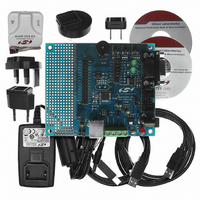
DEV KIT FOR C8051F320/F321
Manufacturer
Silicon Laboratories Inc
Type
MCUr
Specifications of C8051F320DK
Contents
Evaluation Board, Power Supply, USB Cables, Adapter and Documentation
Processor To Be Evaluated
C8051F320/F321
Interface Type
USB
Silicon Manufacturer
Silicon Labs
Core Architecture
8051
Silicon Core Number
C8051F320
Silicon Family Name
C8051F32x
Lead Free Status / RoHS Status
Contains lead / RoHS non-compliant
For Use With/related Products
Silicon Laboratories C8051F320, C8051F321
Lead Free Status / Rohs Status
Lead free / RoHS Compliant
Other names
336-1260
Available stocks
Company
Part Number
Manufacturer
Quantity
Price
Company:

Part Number:
C8051F320DK
Manufacturer:
SiliconL
Quantity:
4


C8051F320/1
15.13. Controlling Endpoints1–3 OUT
Endpoints1-3 OUT are managed via USB registers EOUTCSRL and EOUTCSRH. All OUT endpoints can
be used for Interrupt, Bulk, or Isochronous transfers. Isochronous (ISO) mode is enabled by writing ‘1’ to
the ISO bit in register EOUTCSRH. Bulk and Interrupt transfers are handled identically by hardware.
An Endpoint1-3 OUT interrupt may be generated by the following:
15.13.1.Endpoints1-3 OUT Interrupt or Bulk Mode
When the ISO bit (EOUTCSRH.6) = ‘0’ the target endpoint operates in Bulk or Interrupt mode. Once an
endpoint has been configured to operate in Bulk/Interrupt OUT mode (typically following an Endpoint0
SET_INTERFACE command), hardware will set the OPRDY bit (EOUTCSRL.0) to ‘1’ and generate an
interrupt upon reception of an OUT token and data packet. The number of bytes in the current OUT data
packet (the packet ready to be unloaded from the FIFO) is given in the EOUTCNTH and EOUTCNTL reg-
isters. In response to this interrupt, firmware should unload the data packet from the OUT FIFO and reset
the OPRDY bit to ‘0’.
164
Bit7:
Bit6:
Bit5:
Bit4:
Bit3:
Bit2:
Bits1–0: Unused. Read = 00b; Write = don’t care.
USB Register Definition 15.20. EINCSRH: USB0 IN Endpoint Control High Byte
DBIEN
R/W
Bit7
1. Hardware sets the OPRDY bit (EINCSRL.0) to ‘1’.
2. Hardware generates a STALL condition.
DBIEN: IN Endpoint Double-buffer Enable.
0: Double-buffering disabled for the selected IN endpoint.
1: Double-buffering enabled for the selected IN endpoint.
ISO: Isochronous Transfer Enable.
This bit enables/disables isochronous transfers on the current endpoint.
0: Endpoint configured for bulk/interrupt transfers.
1: Endpoint configured for isochronous transfers.
DIRSEL: Endpoint Direction Select.
This bit is valid only when the selected FIFO is not split (SPLIT = ‘0’).
0: Endpoint direction selected as OUT.
1: Endpoint direction selected as IN.
Unused. Read = ‘0b’. Write = don’t care.
FCDT: Force Data Toggle.
0: Endpoint data toggle switches only when an ACK is received following a data packet
transmission.
1: Endpoint data toggle forced to switch after every data packet is transmitted, regardless of
ACK reception.
SPLIT: FIFO Split Enable.
When SPLIT = ‘1’, the selected endpoint FIFO is split. The upper half of the selected FIFO is
used by the IN endpoint; the lower half of the selected FIFO is used by the OUT endpoint.
ISO
R/W
Bit6
DIRSEL
R/W
Bit5
Bit4
R
-
Rev. 1.4
FCDT
R/W
Bit3
SPLIT
R/W
Bit2
Bit1
R
-
Bit0
R
-
USB Address:
00000000
Reset Value
0x12
Related parts for C8051F320DK
Image
Part Number
Description
Manufacturer
Datasheet
Request
R

Part Number:
Description:
SMD/C°/SINGLE-ENDED OUTPUT SILICON OSCILLATOR
Manufacturer:
Silicon Laboratories Inc
Part Number:
Description:
Manufacturer:
Silicon Laboratories Inc
Datasheet:
Part Number:
Description:
N/A N/A/SI4010 AES KEYFOB DEMO WITH LCD RX
Manufacturer:
Silicon Laboratories Inc
Datasheet:
Part Number:
Description:
N/A N/A/SI4010 SIMPLIFIED KEY FOB DEMO WITH LED RX
Manufacturer:
Silicon Laboratories Inc
Datasheet:
Part Number:
Description:
N/A/-40 TO 85 OC/EZLINK MODULE; F930/4432 HIGH BAND (REV E/B1)
Manufacturer:
Silicon Laboratories Inc
Part Number:
Description:
EZLink Module; F930/4432 Low Band (rev e/B1)
Manufacturer:
Silicon Laboratories Inc
Part Number:
Description:
I°/4460 10 DBM RADIO TEST CARD 434 MHZ
Manufacturer:
Silicon Laboratories Inc
Part Number:
Description:
I°/4461 14 DBM RADIO TEST CARD 868 MHZ
Manufacturer:
Silicon Laboratories Inc
Part Number:
Description:
I°/4463 20 DBM RFSWITCH RADIO TEST CARD 460 MHZ
Manufacturer:
Silicon Laboratories Inc
Part Number:
Description:
I°/4463 20 DBM RADIO TEST CARD 868 MHZ
Manufacturer:
Silicon Laboratories Inc
Part Number:
Description:
I°/4463 27 DBM RADIO TEST CARD 868 MHZ
Manufacturer:
Silicon Laboratories Inc
Part Number:
Description:
I°/4463 SKYWORKS 30 DBM RADIO TEST CARD 915 MHZ
Manufacturer:
Silicon Laboratories Inc
Part Number:
Description:
N/A N/A/-40 TO 85 OC/4463 RFMD 30 DBM RADIO TEST CARD 915 MHZ
Manufacturer:
Silicon Laboratories Inc
Part Number:
Description:
I°/4463 20 DBM RADIO TEST CARD 169 MHZ
Manufacturer:
Silicon Laboratories Inc