C8051F320DK Silicon Laboratories Inc, C8051F320DK Datasheet - Page 220
C8051F320DK
Manufacturer Part Number
C8051F320DK
Description
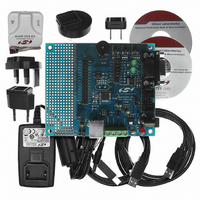
DEV KIT FOR C8051F320/F321
Manufacturer
Silicon Laboratories Inc
Type
MCUr
Specifications of C8051F320DK
Contents
Evaluation Board, Power Supply, USB Cables, Adapter and Documentation
Processor To Be Evaluated
C8051F320/F321
Interface Type
USB
Silicon Manufacturer
Silicon Labs
Core Architecture
8051
Silicon Core Number
C8051F320
Silicon Family Name
C8051F32x
Lead Free Status / RoHS Status
Contains lead / RoHS non-compliant
For Use With/related Products
Silicon Laboratories C8051F320, C8051F321
Lead Free Status / Rohs Status
Lead free / RoHS Compliant
Other names
336-1260
Available stocks
Company
Part Number
Manufacturer
Quantity
Price
Company:

Part Number:
C8051F320DK
Manufacturer:
SiliconL
Quantity:
4


C8051F320/1
220
Bit7:
Bit6:
Bit5:
Bit4:
Bit3:
Bit2:
Bit1:
Bit0:
TF2H
R/W
Bit7
TR2: Timer 2 Run Control.
TF2H: Timer 2 High Byte Overflow Flag.
Set by hardware when the Timer 2 high byte overflows from 0xFF to 0x00. In 16 bit mode,
this will occur when Timer 2 overflows from 0xFFFF to 0x0000. When the Timer 2 interrupt is
enabled, setting this bit causes the CPU to vector to the Timer 2 interrupt service routine.
TF2H is not automatically cleared by hardware and must be cleared by software.
TF2L: Timer 2 Low Byte Overflow Flag.
Set by hardware when the Timer 2 low byte overflows from 0xFF to 0x00. When this bit is
set, an interrupt will be generated if TF2LEN is set and Timer 2 interrupts are enabled. TF2L
will set when the low byte overflows regardless of the Timer 2 mode. This bit is not automat-
ically cleared by hardware.
TF2LEN: Timer 2 Low Byte Interrupt Enable.
This bit enables/disables Timer 2 Low Byte interrupts. If TF2LEN is set and Timer 2 inter-
rupts are enabled, an interrupt will be generated when the low byte of Timer 2 overflows.
0: Timer 2 Low Byte interrupts disabled.
1: Timer 2 Low Byte interrupts enabled.
T2SOF: Timer 2 Start-Of-Frame Capture Enable
0: SOF Capture disabled.
1: SOF Capture enabled. Each time a USB SOF is received, the contents of the Timer 2 reg-
isters (TMR2H and TMR2L) are latched into the Timer 2 reload registers (TMR2RLH and
TMR2RLH), and a Timer 2 interrupt is generated (if enabled).
T2SPLIT: Timer 2 Split Mode Enable.
When this bit is set, Timer 2 operates as two 8-bit timers with auto-reload.
0: Timer 2 operates in 16-bit auto-reload mode.
1: Timer 2 operates as two 8-bit auto-reload timers.
This bit enables/disables Timer 2. In 8-bit mode, this bit enables/disables TMR2H only;
TMR2L is always enabled in this mode.
0: Timer 2 disabled.
1: Timer 2 enabled.
UNUSED. Read = 0b. Write = don’t care.
T2XCLK: Timer 2 External Clock Select.
This bit selects the external clock source for Timer 2. If Timer 2 is in 8-bit mode, this bit
selects the external oscillator clock source for both timer bytes. However, the Timer 2 Clock
Select bits (T2MH and T2ML in register CKCON) may still be used to select between the
external clock and the system clock for either timer.
0: Timer 2 external clock selection is the system clock divided by 12.
1: Timer 2 external clock selection is the external clock divided by 8. Note that the external
oscillator source divided by 8 is synchronized with the system clock.
TF2L
R/W
Bit6
SFR Definition 19.8.
TF2LEN
R/W
Bit5
T2SOF
R/W
Bit4
T2SPLIT
Rev. 1.4
TMR2CN: Timer 2 Control
R/W
Bit3
TR2
R/W
Bit2
R/W
Bit1
-
(bit addressable)
T2XCLK
R/W
Bit0
SFR Address:
00000000
Reset Value
0xC8
Related parts for C8051F320DK
Image
Part Number
Description
Manufacturer
Datasheet
Request
R

Part Number:
Description:
SMD/C°/SINGLE-ENDED OUTPUT SILICON OSCILLATOR
Manufacturer:
Silicon Laboratories Inc
Part Number:
Description:
Manufacturer:
Silicon Laboratories Inc
Datasheet:
Part Number:
Description:
N/A N/A/SI4010 AES KEYFOB DEMO WITH LCD RX
Manufacturer:
Silicon Laboratories Inc
Datasheet:
Part Number:
Description:
N/A N/A/SI4010 SIMPLIFIED KEY FOB DEMO WITH LED RX
Manufacturer:
Silicon Laboratories Inc
Datasheet:
Part Number:
Description:
N/A/-40 TO 85 OC/EZLINK MODULE; F930/4432 HIGH BAND (REV E/B1)
Manufacturer:
Silicon Laboratories Inc
Part Number:
Description:
EZLink Module; F930/4432 Low Band (rev e/B1)
Manufacturer:
Silicon Laboratories Inc
Part Number:
Description:
I°/4460 10 DBM RADIO TEST CARD 434 MHZ
Manufacturer:
Silicon Laboratories Inc
Part Number:
Description:
I°/4461 14 DBM RADIO TEST CARD 868 MHZ
Manufacturer:
Silicon Laboratories Inc
Part Number:
Description:
I°/4463 20 DBM RFSWITCH RADIO TEST CARD 460 MHZ
Manufacturer:
Silicon Laboratories Inc
Part Number:
Description:
I°/4463 20 DBM RADIO TEST CARD 868 MHZ
Manufacturer:
Silicon Laboratories Inc
Part Number:
Description:
I°/4463 27 DBM RADIO TEST CARD 868 MHZ
Manufacturer:
Silicon Laboratories Inc
Part Number:
Description:
I°/4463 SKYWORKS 30 DBM RADIO TEST CARD 915 MHZ
Manufacturer:
Silicon Laboratories Inc
Part Number:
Description:
N/A N/A/-40 TO 85 OC/4463 RFMD 30 DBM RADIO TEST CARD 915 MHZ
Manufacturer:
Silicon Laboratories Inc
Part Number:
Description:
I°/4463 20 DBM RADIO TEST CARD 169 MHZ
Manufacturer:
Silicon Laboratories Inc