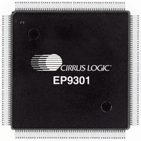
EP9301-CQZ Cirrus Logic Inc, EP9301-CQZ Datasheet - Page 769

EP9301-CQZ
Manufacturer Part Number
EP9301-CQZ
Description
IC ARM9 SOC PROCESSOR 208LQFP
Manufacturer
Cirrus Logic Inc
Series
EP9r
Specifications of EP9301-CQZ
Core Size
16/32-Bit
Peripherals
AC'97, DMA, I²:S, LED, MaverickKey, POR, PWM, WDT
Core Processor
ARM9
Speed
166MHz
Connectivity
EBI/EMI, Ethernet, I²C, IrDA, SPI, UART/USART, USB
Number Of I /o
19
Program Memory Type
ROMless
Ram Size
32K x 8
Voltage - Supply (vcc/vdd)
1.65 V ~ 3.6 V
Data Converters
A/D 5x12b
Oscillator Type
External
Operating Temperature
0°C ~ 70°C
Package / Case
208-TQFP, 208-VQFP
Controller Family/series
(ARM9)
No. Of I/o's
19
Ram Memory Size
16MB
Cpu Speed
166MHz
No. Of Timers
4
Digital Ic Case Style
TQFP
Embedded Interface Type
SPI
Rohs Compliant
Yes
Processor Series
EP93xx
Core
ARM920T
Data Bus Width
32 bit
3rd Party Development Tools
MDK-ARM, RL-ARM, ULINK2
Lead Free Status / RoHS Status
Lead free / RoHS Compliant
Eeprom Size
-
Program Memory Size
-
Lead Free Status / Rohs Status
Details
Other names
598-1136
Available stocks
Company
Part Number
Manufacturer
Quantity
Price
Company:
Part Number:
EP9301-CQZ
Manufacturer:
CIRRUS
Quantity:
3 390
Part Number:
EP9301-CQZ
Manufacturer:
CIRRUSLOGIC
Quantity:
20 000
Company:
Part Number:
EP9301-CQZR
Manufacturer:
Cirrus Logic Inc
Quantity:
10 000
- Current page: 769 of 824
- Download datasheet (13Mb)
DS785UM1
Address:
Default:
Definition:
Bit Descriptions:
0x808F_0000
0x0000_0000
Key scan initialization register.
RSVD:
DBNC:
DIS3KY:
DIAG:
BACK:
T2:
NA:
Copyright 2007 Cirrus Logic
Reserved. Unknown during read.
De-bounce start count. This value is used to pre-load the
de-bounce counter. The de-bounce counter counts the
number of consecutive scans that decoded the same
keys. Terminal count for the de-bounce counter is 0xFF.
Terminal count indirectly generates a key scan interrupt. A
pre-load value of 0xFC will cause the key scan circuitry to
count 3 identical consecutive keypad scans.
Disable 3 Key reset. Setting this bit high disables the three
key reset output to the watchdog reset block. Setting it
back low re-enables it.
Key scan diagnostic mode. Setting this bit high allows key
scanning to be directly controlled through the key register
by writes from the ARM Core. The DIAG.KEY[5:0] value is
written by the ARM Core. Then the KeyRegister.K bit is
read to determine if there is a key press. The result from
reading the KeyRegister.K bit is not hardware de-bounced.
Key scan back driving enable. Setting this bit high enables
the key scanning logic to back drive the row and column
pins of the chip high during the first two column counts in
the row/column counter.
Test mode bit. When this bit is set to “1”, the counter
RC_COUNT is advanced by 8 counts when EN is active.
The effect is that only column 0 is checked in each row.
This test mode allows a faster test of the ROW pins.
Not Assigned. These bits will read back the value written.
EP93xx User’s Guide
Keypad Interface
26-7
26
Related parts for EP9301-CQZ
Image
Part Number
Description
Manufacturer
Datasheet
Request
R

Part Number:
Description:
32-Bit Microcontroller IC
Manufacturer:
Cirrus Logic Inc
Datasheet:

Part Number:
Description:
IC ARM920T MCU 166MHZ 208-LQFP
Manufacturer:
Cirrus Logic Inc
Datasheet:

Part Number:
Description:
IC ARM920T MCU 166MHZ 208-LQFP
Manufacturer:
Cirrus Logic Inc
Datasheet:

Part Number:
Description:
Development Kit
Manufacturer:
Cirrus Logic Inc
Datasheet:

Part Number:
Description:
Development Kit
Manufacturer:
Cirrus Logic Inc
Datasheet:

Part Number:
Description:
High-efficiency PFC + Fluorescent Lamp Driver Reference Design
Manufacturer:
Cirrus Logic Inc
Datasheet:

Part Number:
Description:
Development Kit
Manufacturer:
Cirrus Logic Inc
Datasheet:

Part Number:
Description:
Development Kit
Manufacturer:
Cirrus Logic Inc
Datasheet:

Part Number:
Description:
Development Kit
Manufacturer:
Cirrus Logic Inc
Datasheet:

Part Number:
Description:
Development Kit
Manufacturer:
Cirrus Logic Inc
Datasheet:

Part Number:
Description:
Development Kit
Manufacturer:
Cirrus Logic Inc
Datasheet:

Part Number:
Description:
Development Kit
Manufacturer:
Cirrus Logic Inc
Datasheet:

Part Number:
Description:
Ref Bd For Speakerbar MSA & DSP Products
Manufacturer:
Cirrus Logic Inc


