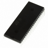
ST72F324BJ6B6 STMicroelectronics, ST72F324BJ6B6 Datasheet - Page 150

ST72F324BJ6B6
Manufacturer Part Number
ST72F324BJ6B6
Description
MCU 8BIT 32KB FLASH/ROM 42-SDIP
Manufacturer
STMicroelectronics
Series
ST7r
Datasheet
1.ST72F324BJ6B6.pdf
(193 pages)
Specifications of ST72F324BJ6B6
Core Processor
ST7
Core Size
8-Bit
Speed
8MHz
Connectivity
SCI, SPI
Peripherals
LVD, POR, PWM, WDT
Number Of I /o
32
Program Memory Size
32KB (32K x 8)
Program Memory Type
FLASH
Ram Size
1K x 8
Voltage - Supply (vcc/vdd)
3.8 V ~ 5.5 V
Data Converters
A/D 12x10b
Oscillator Type
Internal
Operating Temperature
-40°C ~ 85°C
Package / Case
42-SDIP (0.600", 15.24mm)
Controller Family/series
ST7
No. Of I/o's
32
Ram Memory Size
1KB
Cpu Speed
8MHz
No. Of Timers
2
Embedded Interface Type
SCI, SPI
No. Of Pwm Channels
3
Processor Series
ST72F3x
Core
ST7
Data Bus Width
8 bit
Data Ram Size
1 KB
Interface Type
SCI, SPI
Maximum Clock Frequency
8 MHz
Number Of Programmable I/os
32
Number Of Timers
3
Maximum Operating Temperature
+ 85 C
Mounting Style
Through Hole
Development Tools By Supplier
ST7232X-EVAL, ST7MDT20-DVP3, ST7MDT20J-EMU3, STX-RLINK
Minimum Operating Temperature
- 40 C
On-chip Adc
10 bit, 12 Channel
For Use With
497-6421 - BOARD EVAL DGTL BATT CHGR DESIGN497-5046 - KIT TOOL FOR ST7/UPSD/STR7 MCU
Lead Free Status / RoHS Status
Lead free / RoHS Compliant
Eeprom Size
-
Lead Free Status / Rohs Status
Details
Other names
497-5589-5
- Current page: 150 of 193
- Download datasheet (3Mb)
Electrical characteristics
12.6.3
150/193
Crystal and ceramic resonator oscillators
The ST7 internal clock can be supplied with four different crystal/ceramic resonator
oscillators. All the information given in this paragraph are based on characterization results
with specified typical external components. In the application, the resonator and the load
capacitors have to be placed as close as possible to the oscillator pins in order to minimize
output distortion and start-up stabilization time. Refer to the crystal/ceramic resonator
manufacturer for more details (frequency, package, accuracy...).
8/16 Kbyte Flash and ROM devices
Table 95.
1. The oscillator selection can be optimized in terms of supply current using an high quality resonator with
2. Data based on characterization results, not tested in production. The relatively low value of the RF resistor,
3. For C
Symbol
f
C
C
OSC
R
small R
offers a good protection against issues resulting from use in a humid environment, due to the induced
leakage and the bias condition change. However, it is recommended to take this point into account if the
microcontroller is used in tough humidity conditions.
designed for high-frequency applications and selected to match the requirements of the crystal or
resonator. C
capacitance which is the series combination of C
included when sizing C
capacitance).
i
L1
L2
2
F
L1
S
Oscillator frequency
Feedback resistor
Recommended load capacitance
versus equivalent serial
resistance of the crystal or
ceramic resonator (R
OSC2 driving current
and C
value. Refer to crystal/ceramic resonator manufacturer for more details.
Crystal and ceramic resonator oscillators (8/16 Kbyte Flash and ROM
devices)
L1
L2
and C
it is recommended to use high-quality ceramic capacitors in the 5 pF to 25 pF range (typ.)
Parameter
L2
, are usually the same size. The crystal manufacturer typically specifies a load
L1
and C
(2)
(1)
S
L2
)
(3)
(10 pF can be used as a rough estimate of the combined pin and board
LP: low power oscillator
MP: medium power oscillator
MS: medium speed oscillator
HS: high speed oscillator
R
R
R
R
V
L1
DD
S
S
S
S
and C
= 200 Ω
= 200 Ω
= 200 Ω
= 100 Ω
= 5V, V
L2
Conditions
. PCB and MCU pin capacitance must be
IN
= V
LP oscillator
MP oscillator
MS oscillator
HS oscillator
LP oscillator
MP oscillator
MS oscillator
HS oscillator
SS
Min Typ Max Unit
>2
>4
>8
20
22
22
18
15
1
160
310
610
80
ST72324Bxx
150
250
460
910
16
40
56
46
33
33
2
4
8
MHz
kΩ
pF
µA
Related parts for ST72F324BJ6B6
Image
Part Number
Description
Manufacturer
Datasheet
Request
R

Part Number:
Description:
STMicroelectronics [RIPPLE-CARRY BINARY COUNTER/DIVIDERS]
Manufacturer:
STMicroelectronics
Datasheet:

Part Number:
Description:
STMicroelectronics [LIQUID-CRYSTAL DISPLAY DRIVERS]
Manufacturer:
STMicroelectronics
Datasheet:

Part Number:
Description:
BOARD EVAL FOR MEMS SENSORS
Manufacturer:
STMicroelectronics
Datasheet:

Part Number:
Description:
NPN TRANSISTOR POWER MODULE
Manufacturer:
STMicroelectronics
Datasheet:

Part Number:
Description:
TURBOSWITCH ULTRA-FAST HIGH VOLTAGE DIODE
Manufacturer:
STMicroelectronics
Datasheet:

Part Number:
Description:
Manufacturer:
STMicroelectronics
Datasheet:

Part Number:
Description:
DIODE / SCR MODULE
Manufacturer:
STMicroelectronics
Datasheet:

Part Number:
Description:
DIODE / SCR MODULE
Manufacturer:
STMicroelectronics
Datasheet:

Part Number:
Description:
Search -----> STE16N100
Manufacturer:
STMicroelectronics
Datasheet:

Part Number:
Description:
Search ---> STE53NA50
Manufacturer:
STMicroelectronics
Datasheet:

Part Number:
Description:
NPN Transistor Power Module
Manufacturer:
STMicroelectronics
Datasheet:


