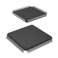
HD64F2378RVFQ33 Renesas Electronics America, HD64F2378RVFQ33 Datasheet - Page 845

HD64F2378RVFQ33
Manufacturer Part Number
HD64F2378RVFQ33
Description
IC H8S MCU FLASH 512K 144-LQFP
Manufacturer
Renesas Electronics America
Series
H8® H8S/2300r
Specifications of HD64F2378RVFQ33
Core Processor
H8S/2000
Core Size
16-Bit
Speed
33MHz
Connectivity
I²C, IrDA, SCI, SmartCard
Peripherals
DMA, POR, PWM, WDT
Number Of I /o
97
Program Memory Size
512KB (512K x 8)
Program Memory Type
FLASH
Ram Size
32K x 8
Voltage - Supply (vcc/vdd)
3 V ~ 3.6 V
Data Converters
A/D 16x10b; D/A 6x8b
Oscillator Type
Internal
Operating Temperature
-20°C ~ 75°C
Package / Case
144-LQFP
Lead Free Status / RoHS Status
Contains lead / RoHS non-compliant
Eeprom Size
-
- Current page: 845 of 1208
- Download datasheet (8Mb)
16.3.2
ICCRB is an 8-bit readable/writable register that issues start/stop conditions, manipulates the SDA
pin, monitors the SCL pin, and controls reset in I
Bit
7
6
5
4
3
2
Bit Name
BBSY
SCP
SDAO
⎯
SCLO
⎯
I
2
C Bus Control Register B (ICCRB)
Initial Value
0
1
1
1
1
1
R/W
R/W
W
R/W
R/W
R
⎯
Description
Bus Busy
This bit enables to confirm whether the I
occupied or released and to issue start and stop
conditions in master mode. This bit is set to 1 when
the SDA level changes from high to low under the
condition of SCL = high, assuming that the start
condition has been issued. This bit is cleared to 0
when the SDA level changes from low to high
under the condition of SCL = high, assuming that
the stop condition has been issued. Write 1 to
BBSY and 0 to SCP to issue a start condition.
Follow this procedure when also re-transmitting a
start condition. Write 0 to BBSY and 0 to SCP to
issue a stop condition. To issue a start/stop
condition, use the MOV instruction.
Start Condition/Stop Condition Prohibit
The SCP bit controls the issue of start/stop
conditions in master mode.
To issue a start condition, write 1 in BBSY and 0 in
SCP. A retransmit start condition is issued in the
same way. To issue a stop condition, write 0 in
BBSY and 0 in SCP. This bit is always read as 1. If
1 is written, the data is not stored.
Monitors the output level of SDA.
0: When reading, SDA pin outputs low.
1: When reading, SDA pin outputs high.
The write value must always be 1.
Reserved
The write value must always be 1.
This bit monitors SCL output level. When reading
and SCLO is 1, SCL pin outputs high. When
reading and SCLO is 0, SCL pin outputs low.
Reserved
This bit is always read as 1.
2
C control.
Section 16 I
Rev.7.00 Mar. 18, 2009 page 777 of 1136
2
C Bus Interface 2 (IIC2) (Option)
REJ09B0109-0700
2
C bus is
Related parts for HD64F2378RVFQ33
Image
Part Number
Description
Manufacturer
Datasheet
Request
R

Part Number:
Description:
KIT STARTER FOR M16C/29
Manufacturer:
Renesas Electronics America
Datasheet:

Part Number:
Description:
KIT STARTER FOR R8C/2D
Manufacturer:
Renesas Electronics America
Datasheet:

Part Number:
Description:
R0K33062P STARTER KIT
Manufacturer:
Renesas Electronics America
Datasheet:

Part Number:
Description:
KIT STARTER FOR R8C/23 E8A
Manufacturer:
Renesas Electronics America
Datasheet:

Part Number:
Description:
KIT STARTER FOR R8C/25
Manufacturer:
Renesas Electronics America
Datasheet:

Part Number:
Description:
KIT STARTER H8S2456 SHARPE DSPLY
Manufacturer:
Renesas Electronics America
Datasheet:

Part Number:
Description:
KIT STARTER FOR R8C38C
Manufacturer:
Renesas Electronics America
Datasheet:

Part Number:
Description:
KIT STARTER FOR R8C35C
Manufacturer:
Renesas Electronics America
Datasheet:

Part Number:
Description:
KIT STARTER FOR R8CL3AC+LCD APPS
Manufacturer:
Renesas Electronics America
Datasheet:

Part Number:
Description:
KIT STARTER FOR RX610
Manufacturer:
Renesas Electronics America
Datasheet:

Part Number:
Description:
KIT STARTER FOR R32C/118
Manufacturer:
Renesas Electronics America
Datasheet:

Part Number:
Description:
KIT DEV RSK-R8C/26-29
Manufacturer:
Renesas Electronics America
Datasheet:

Part Number:
Description:
KIT STARTER FOR SH7124
Manufacturer:
Renesas Electronics America
Datasheet:

Part Number:
Description:
KIT STARTER FOR H8SX/1622
Manufacturer:
Renesas Electronics America
Datasheet:

Part Number:
Description:
KIT DEV FOR SH7203
Manufacturer:
Renesas Electronics America
Datasheet:


