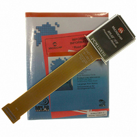
PCM18XT0 Microchip Technology, PCM18XT0 Datasheet - Page 349

PCM18XT0
Manufacturer Part Number
PCM18XT0
Description
MODULE PROC PIC18F4685
Manufacturer
Microchip Technology
Datasheet
1.PCM18XT0.pdf
(484 pages)
Specifications of PCM18XT0
Accessory Type
Processor Module
Product
Microcontroller Modules
Core Processor
PIC18F4685
Lead Free Status / RoHS Status
Not applicable / Not applicable
For Use With/related Products
ICE2000
For Use With
ICE2000 - EMULATOR MPLAB-ICE 2000 POD
Lead Free Status / RoHS Status
Lead free / RoHS Compliant, Not applicable / Not applicable
- Current page: 349 of 484
- Download datasheet (9Mb)
REGISTER 24-4:
REGISTER 24-5:
© 2009 Microchip Technology Inc.
bit 7
Legend:
R = Readable bit
-n = Value when device is unprogrammed
bit 7
bit 6-3
bit 2
bit 1
bit 0
bit 7
Legend:
R = Readable bit
-n = Value when device is unprogrammed
bit 7
bit 6
bit 5
bit 4
bit 3
bit 2
bit 1
bit 0
MCLRE
DEBUG
R/P-1
R/P-1
MCLRE: MCLR Pin Enable bit
1 = MCLR pin enabled; RE3 input pin disabled
0 = RE3 input pin enabled; MCLR disabled
Unimplemented: Read as ‘0’
LPT1OSC: Low-Power Timer1 Oscillator Enable bit
1 = Timer1 configured for low-power operation
0 = Timer1 configured for higher power operation
PBADEN: PORTB A/D Enable bit
(Affects ADCON1 Reset state. ADCON1 controls PORTB<4:0> pin configuration.)
1 = PORTB<4:0> pins are configured as analog input channels on Reset
0 = PORTB<4:0> pins are configured as digital I/O on Reset
Unimplemented: Read as ‘0’
DEBUG: Background Debugger Enable bit
1 = Background debugger disabled, RB6 and RB7 configured as general purpose I/O pins
0 = Background debugger enabled, RB6 and RB7 are dedicated to In-Circuit Debug
XINST: Extended Instruction Set Enable bit
1 = Instruction set extension and Indexed Addressing mode enabled
0 = Instruction set extension and Indexed Addressing mode disabled (Legacy mode)
BBSIZ1: Boot Block Size Select Bit 1
11 = 4K words (8 Kbytes) boot block
10 = 4K words (8 Kbytes) boot block
BBSIZ2: Boot Block Size Select Bit 0
01 = 2K words (4 Kbytes) boot block
00 = 1K words (2 Kbytes) boot block
Unimplemented: Read as ‘0’
LVP: Single-Supply ICSP™ Enable bit
1 = Single-Supply ICSP enabled
0 = Single-Supply ICSP disabled
Unimplemented: Read as ‘0’
STVREN: Stack Full/Underflow Reset Enable bit
1 = Stack full/underflow will cause Reset
0 = Stack full/underflow will not cause Reset
XINST
R/P-0
U-0
—
CONFIG3H: CONFIGURATION REGISTER 3 HIGH (BYTE ADDRESS 300005h)
CONFIG4L: CONFIGURATION REGISTER 4 LOW (BYTE ADDRESS 300006h)
P = Programmable bit
P = Programmable bit
BBSIZ1
R/P-0
U-0
—
PIC18F2682/2685/4682/4685
BBSIZ2
R/P-0
U-0
—
U = Unimplemented bit, read as ‘0’
u = Unchanged from programmed state
U = Unimplemented bit, read as ‘0’
u = Unchanged from programmed state
U-0
U-0
—
—
LPT1OSC
R/P-0
R/P-1
LVP
PBADEN
R/P-1
U-0
—
DS39761C-page 349
STVREN
R/P-1
U-0
—
bit 0
bit 0
Related parts for PCM18XT0
Image
Part Number
Description
Manufacturer
Datasheet
Request
R

Part Number:
Description:
Manufacturer:
Microchip Technology Inc.
Datasheet:

Part Number:
Description:
Manufacturer:
Microchip Technology Inc.
Datasheet:

Part Number:
Description:
Manufacturer:
Microchip Technology Inc.
Datasheet:

Part Number:
Description:
Manufacturer:
Microchip Technology Inc.
Datasheet:

Part Number:
Description:
Manufacturer:
Microchip Technology Inc.
Datasheet:

Part Number:
Description:
Manufacturer:
Microchip Technology Inc.
Datasheet:

Part Number:
Description:
Manufacturer:
Microchip Technology Inc.
Datasheet:

Part Number:
Description:
Manufacturer:
Microchip Technology Inc.
Datasheet:


