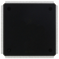
MCF5407AI220 Freescale Semiconductor, MCF5407AI220 Datasheet - Page 128

MCF5407AI220
Manufacturer Part Number
MCF5407AI220
Description
IC MPU 32B 220MHZ COLDF 208-FQFP
Manufacturer
Freescale Semiconductor
Series
MCF540xr
Specifications of MCF5407AI220
Core Processor
Coldfire V4
Core Size
32-Bit
Speed
220MHz
Connectivity
EBI/EMI, I²C, UART/USART
Peripherals
DMA, WDT
Number Of I /o
16
Program Memory Type
ROMless
Ram Size
4K x 8
Voltage - Supply (vcc/vdd)
1.65 V ~ 3.6 V
Oscillator Type
External
Operating Temperature
0°C ~ 70°C
Package / Case
208-FQFP
Maximum Clock Frequency
220 MHz
Operating Supply Voltage
1.8 V, 3.3 V
Maximum Operating Temperature
+ 105 C
Mounting Style
SMD/SMT
Minimum Operating Temperature
0 C
Program Memory Size
24KB
Cpu Speed
220MHz
Embedded Interface Type
I2C, UART
Digital Ic Case Style
FQFP
No. Of Pins
208
Supply Voltage Range
3.3V
Rohs Compliant
Yes
For Use With
M5407C3 - KIT EVAL FOR MCF5407 W/ETHERNET
Lead Free Status / RoHS Status
Lead free / RoHS Compliant
Eeprom Size
-
Program Memory Size
-
Data Converters
-
Lead Free Status / Rohs Status
Lead free / RoHS Compliant
Available stocks
Company
Part Number
Manufacturer
Quantity
Price
Company:
Part Number:
MCF5407AI220
Manufacturer:
freescaie
Quantity:
6
Company:
Part Number:
MCF5407AI220
Manufacturer:
Freescale Semiconductor
Quantity:
135
Company:
Part Number:
MCF5407AI220
Manufacturer:
FREESCALE
Quantity:
1 831
Company:
Part Number:
MCF5407AI220
Manufacturer:
Freescale Semiconductor
Quantity:
10 000
- Current page: 128 of 546
- Download datasheet (7Mb)
SRAM Initialization
The mapping of a given access into the RAM uses the following algorithm to determine if
the access hits in the memory:
if (RAMBAR[0] = 1)
if (((access = instructionFetch) & (RAMBAR[7] = 1)) |
ASn refers to the five address space mask bits: C/I, SC, SD, UC, and UD.
4.5 SRAM Initialization
After a hardware reset, the contents of each SRAM module are undefined. The valid bits,
RAMBARn[V], are cleared, disabling the SRAM modules. If the SRAM requires
initialization with instructions or data, the following steps should be performed:
4-4
6
5–1
0
Bits
1. Load RAMBARn with bit 7 = 0, mapping the SRAM module to the desired location.
Clearing RAMBARn[7] logically connects the SRAM module to the processor’s
data bus.
—
C/I,
SC,
SD,
UC,
UD
V
Name
((access = dataReference)
if (requested address[31:n] = RAMBAR[31:n]
Reserved, should be cleared.
Address space masks (ASn). These fields allow certain types of accesses to be masked, or
inhibited from accessing the SRAM module. These bits are useful for power management as
described in Section 4.6, “Power Management.” In particular, C/I is typically set.
The address space mask bits are follows:
C/I = CPU space/interrupt acknowledge cycle mask. Note that C/I must be set if BA = 0.
SC = Supervisor code address space mask
SD = Supervisor data address space mask
UC = User code address space mask
UD = User data address space mask
For each ASn bit:
0 An access to the SRAM module can occur for this address space
1 Disable this address space from the SRAM module. If a reference using this address space is
Valid. Enables/disables the SRAM module. V is cleared at reset.
0 RAMBAR contents are not valid.
1 RAMBAR contents are valid.
made, it is inhibited from accessing the SRAM module and is processed like any other
non-SRAM reference.
Table 4-1. RAMBARn Field Description (Continued)
if (requested address[31:10] = RAMBAR[31:10])
if (ASn of the requested type = 0)
Access is mapped to the RAM module
if (access = read)
if (access = write)
MCF5407 User’s Manual
Read the RAM and return the data
if (RAMBAR[8] = 0)
else Signal a write-protect access error
& (RAMBAR[7] = 0)))
Write the data into the RAM
Description
Related parts for MCF5407AI220
Image
Part Number
Description
Manufacturer
Datasheet
Request
R
Part Number:
Description:
Mcf5407 Coldfire Integrated Microprocessor User
Manufacturer:
Freescale Semiconductor, Inc
Datasheet:
Part Number:
Description:
Manufacturer:
Freescale Semiconductor, Inc
Datasheet:
Part Number:
Description:
Manufacturer:
Freescale Semiconductor, Inc
Datasheet:
Part Number:
Description:
Manufacturer:
Freescale Semiconductor, Inc
Datasheet:
Part Number:
Description:
Manufacturer:
Freescale Semiconductor, Inc
Datasheet:
Part Number:
Description:
Manufacturer:
Freescale Semiconductor, Inc
Datasheet:
Part Number:
Description:
Manufacturer:
Freescale Semiconductor, Inc
Datasheet:
Part Number:
Description:
Manufacturer:
Freescale Semiconductor, Inc
Datasheet:
Part Number:
Description:
Manufacturer:
Freescale Semiconductor, Inc
Datasheet:
Part Number:
Description:
Manufacturer:
Freescale Semiconductor, Inc
Datasheet:
Part Number:
Description:
Manufacturer:
Freescale Semiconductor, Inc
Datasheet:
Part Number:
Description:
Manufacturer:
Freescale Semiconductor, Inc
Datasheet:
Part Number:
Description:
Manufacturer:
Freescale Semiconductor, Inc
Datasheet:
Part Number:
Description:
Manufacturer:
Freescale Semiconductor, Inc
Datasheet:
Part Number:
Description:
Manufacturer:
Freescale Semiconductor, Inc
Datasheet:


