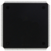
MCF5407AI220 Freescale Semiconductor, MCF5407AI220 Datasheet - Page 513

MCF5407AI220
Manufacturer Part Number
MCF5407AI220
Description
IC MPU 32B 220MHZ COLDF 208-FQFP
Manufacturer
Freescale Semiconductor
Series
MCF540xr
Specifications of MCF5407AI220
Core Processor
Coldfire V4
Core Size
32-Bit
Speed
220MHz
Connectivity
EBI/EMI, I²C, UART/USART
Peripherals
DMA, WDT
Number Of I /o
16
Program Memory Type
ROMless
Ram Size
4K x 8
Voltage - Supply (vcc/vdd)
1.65 V ~ 3.6 V
Oscillator Type
External
Operating Temperature
0°C ~ 70°C
Package / Case
208-FQFP
Maximum Clock Frequency
220 MHz
Operating Supply Voltage
1.8 V, 3.3 V
Maximum Operating Temperature
+ 105 C
Mounting Style
SMD/SMT
Minimum Operating Temperature
0 C
Program Memory Size
24KB
Cpu Speed
220MHz
Embedded Interface Type
I2C, UART
Digital Ic Case Style
FQFP
No. Of Pins
208
Supply Voltage Range
3.3V
Rohs Compliant
Yes
For Use With
M5407C3 - KIT EVAL FOR MCF5407 W/ETHERNET
Lead Free Status / RoHS Status
Lead free / RoHS Compliant
Eeprom Size
-
Program Memory Size
-
Data Converters
-
Lead Free Status / Rohs Status
Lead free / RoHS Compliant
Available stocks
Company
Part Number
Manufacturer
Quantity
Price
Company:
Part Number:
MCF5407AI220
Manufacturer:
freescaie
Quantity:
6
Company:
Part Number:
MCF5407AI220
Manufacturer:
Freescale Semiconductor
Quantity:
135
Company:
Part Number:
MCF5407AI220
Manufacturer:
FREESCALE
Quantity:
1 831
Company:
Part Number:
MCF5407AI220
Manufacturer:
Freescale Semiconductor
Quantity:
10 000
- Current page: 513 of 546
- Download datasheet (7Mb)
frame, shown in Figure A-4.
As part of the Debug C enhancement, the operation of the debug interrupt is modified as
follows:
Implementation of this revised debug interrupt handling fully supports the servicing of any
number of normal interrupt requests while in a debug interrupt service routine. The
emulator mode state bit is essentially changed to a program-visible value, stored into
memory when the exception stack frame is created, and loaded from memory by the RTE
instruction.
+ 0x04
A7→
• The occurrence of the breakpoint trigger, configured to generate a debug interrupt,
• At the appropriate sample point, the processor initiates debug interrupt exception
• All normal interrupt requests are evaluated and sampled once per instruction during
1. In response to the new exception, the processor saves a copy of the current value of
2. The new exception stack frame sets bit 1 of the fault status field, using the saved
3. Control is passed to the appropriate exception handler.
4. When the exception handler is complete, a Return From Exception (RTE)
31
is treated exactly as before. The debug interrupt is treated as a higher priority
exception relative to the normal interrupt requests encoded on the interrupt priority
input signals.
processing. This event is signaled externally by the generation of a unique PST value
(PST = 0xD) asserted for multiple cycles. The processor sets the emulator mode
state bit as part of this processing.
the debug interrupt service routine. If an exception is detected, the processor takes
the following steps:
the emulator mode state bit and then exits emulator mode by clearing the actual
state.
emulator mode bit, indicating that execution while the processor is in emulator mode
was interrupted. This corresponds to bit [17] of the longword at the top of the system
stack.
instruction is executed. During the processing of the RTE, the FS1 bit is reloaded
from the system stack. If FS1 = 1, the processor sets the emulator mode state and
resumes execution of the original debug interrupt service routine. This is signaled
externally by the generation of the PST value that originally identified the
occurrence of a debug interrupt exception, that is, PST = 0xD.
Format
28 27
FS[3–2]
26 25
Appendix A. Migrating from the ColdFire MCF5307 to the MCF5407
Figure A-4. Exception Stack Frame Form
Vector[7–0]
Program counter[31:0]
18
FS[1–0]
17
16
15
Status Register
Revision C Debug
A-11
0
Related parts for MCF5407AI220
Image
Part Number
Description
Manufacturer
Datasheet
Request
R
Part Number:
Description:
Mcf5407 Coldfire Integrated Microprocessor User
Manufacturer:
Freescale Semiconductor, Inc
Datasheet:
Part Number:
Description:
Manufacturer:
Freescale Semiconductor, Inc
Datasheet:
Part Number:
Description:
Manufacturer:
Freescale Semiconductor, Inc
Datasheet:
Part Number:
Description:
Manufacturer:
Freescale Semiconductor, Inc
Datasheet:
Part Number:
Description:
Manufacturer:
Freescale Semiconductor, Inc
Datasheet:
Part Number:
Description:
Manufacturer:
Freescale Semiconductor, Inc
Datasheet:
Part Number:
Description:
Manufacturer:
Freescale Semiconductor, Inc
Datasheet:
Part Number:
Description:
Manufacturer:
Freescale Semiconductor, Inc
Datasheet:
Part Number:
Description:
Manufacturer:
Freescale Semiconductor, Inc
Datasheet:
Part Number:
Description:
Manufacturer:
Freescale Semiconductor, Inc
Datasheet:
Part Number:
Description:
Manufacturer:
Freescale Semiconductor, Inc
Datasheet:
Part Number:
Description:
Manufacturer:
Freescale Semiconductor, Inc
Datasheet:
Part Number:
Description:
Manufacturer:
Freescale Semiconductor, Inc
Datasheet:
Part Number:
Description:
Manufacturer:
Freescale Semiconductor, Inc
Datasheet:
Part Number:
Description:
Manufacturer:
Freescale Semiconductor, Inc
Datasheet:


