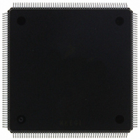
MCF5407AI220 Freescale Semiconductor, MCF5407AI220 Datasheet - Page 356

MCF5407AI220
Manufacturer Part Number
MCF5407AI220
Description
IC MPU 32B 220MHZ COLDF 208-FQFP
Manufacturer
Freescale Semiconductor
Series
MCF540xr
Specifications of MCF5407AI220
Core Processor
Coldfire V4
Core Size
32-Bit
Speed
220MHz
Connectivity
EBI/EMI, I²C, UART/USART
Peripherals
DMA, WDT
Number Of I /o
16
Program Memory Type
ROMless
Ram Size
4K x 8
Voltage - Supply (vcc/vdd)
1.65 V ~ 3.6 V
Oscillator Type
External
Operating Temperature
0°C ~ 70°C
Package / Case
208-FQFP
Maximum Clock Frequency
220 MHz
Operating Supply Voltage
1.8 V, 3.3 V
Maximum Operating Temperature
+ 105 C
Mounting Style
SMD/SMT
Minimum Operating Temperature
0 C
Program Memory Size
24KB
Cpu Speed
220MHz
Embedded Interface Type
I2C, UART
Digital Ic Case Style
FQFP
No. Of Pins
208
Supply Voltage Range
3.3V
Rohs Compliant
Yes
For Use With
M5407C3 - KIT EVAL FOR MCF5407 W/ETHERNET
Lead Free Status / RoHS Status
Lead free / RoHS Compliant
Eeprom Size
-
Program Memory Size
-
Data Converters
-
Lead Free Status / Rohs Status
Lead free / RoHS Compliant
Available stocks
Company
Part Number
Manufacturer
Quantity
Price
Company:
Part Number:
MCF5407AI220
Manufacturer:
freescaie
Quantity:
6
Company:
Part Number:
MCF5407AI220
Manufacturer:
Freescale Semiconductor
Quantity:
135
Company:
Part Number:
MCF5407AI220
Manufacturer:
FREESCALE
Quantity:
1 831
Company:
Part Number:
MCF5407AI220
Manufacturer:
Freescale Semiconductor
Quantity:
10 000
- Current page: 356 of 546
- Download datasheet (7Mb)
Register Descriptions
Table 14-11 describes UCRn fields and commands. Examples in Section 14.5.2,
“Transmitter and Receiver Operating Modes,” show how these commands are used.
7
6–4
14-14
Bits
Value
000
001
010
011
100
101
110
111
—
Address
Reset
Field
R/W
NO COMMAND
RESET MODE
REGISTER POINTER
RESET RECEIVER
RESET
TRANSMITTER
RESET ERROR
STATUS
RESET BREAK
CHANGE INTERRUPT
START BREAK
STOP BREAK
Command
—
—
Figure 14-11. UART Command Register (UCRn)
7
–
Table 14-11. UCRn Field Descriptions
6
Reserved, should be cleared.
—
Causes the mode register pointer to point to UMR1n.
Immediately disables the receiver, clears USRn[FFULL,RxRDY], and reinitializes
the receiver FIFO pointer. No other registers are altered. Because it places the
receiver in a known state, use this command instead of
reconfiguring the receiver.
In UART mode, immediately disables the transmitter and clears
USRn[TxEMP,TxRDY]. No other registers are altered. Because it places the
transmitter in a known state, use this command instead of
when reconfiguring the transmitter. When UART1 is in modem mode, TxEMP is
not cleared by this soft reset. It is cleared the same way as the Rx overflow bit,
by a
In UART mode, clears USRn[RB,FE,PE,OE]. Also used in block mode to clear all
error bits after a data block is received. When UART1 is in modem mode, this
command also clears TxEMP.
Clears the delta break bit, UISRn[DB]. This command has no effect in modem
mode.
Forces TxD low. If the transmitter is empty, the break may be delayed up to one
bit time. If the transmitter is active, the break starts when character transmission
completes. The break is delayed until any character in the transmitter shift
register is sent. Any character in the transmitter holding register is sent after the
break. The transmitter must be enabled for the command to be accepted. This
command ignores the state of CTS and has no effect in modem mode.
Causes TxD to go high (mark) within two bit times. Any characters in the
transmitter buffer are sent.
MISC Field (This field selects a single command.)
RESET ERROR STATUS
MISC
MCF5407 User’s Manual
MBAR + 0x1C8, 0x208
4
0000_0000
Write only
command.
3
Description
TC
2
1
RECEIVER DISABLE
RC
TRANSMITTER DISABLE
0
when
Related parts for MCF5407AI220
Image
Part Number
Description
Manufacturer
Datasheet
Request
R
Part Number:
Description:
Mcf5407 Coldfire Integrated Microprocessor User
Manufacturer:
Freescale Semiconductor, Inc
Datasheet:
Part Number:
Description:
Manufacturer:
Freescale Semiconductor, Inc
Datasheet:
Part Number:
Description:
Manufacturer:
Freescale Semiconductor, Inc
Datasheet:
Part Number:
Description:
Manufacturer:
Freescale Semiconductor, Inc
Datasheet:
Part Number:
Description:
Manufacturer:
Freescale Semiconductor, Inc
Datasheet:
Part Number:
Description:
Manufacturer:
Freescale Semiconductor, Inc
Datasheet:
Part Number:
Description:
Manufacturer:
Freescale Semiconductor, Inc
Datasheet:
Part Number:
Description:
Manufacturer:
Freescale Semiconductor, Inc
Datasheet:
Part Number:
Description:
Manufacturer:
Freescale Semiconductor, Inc
Datasheet:
Part Number:
Description:
Manufacturer:
Freescale Semiconductor, Inc
Datasheet:
Part Number:
Description:
Manufacturer:
Freescale Semiconductor, Inc
Datasheet:
Part Number:
Description:
Manufacturer:
Freescale Semiconductor, Inc
Datasheet:
Part Number:
Description:
Manufacturer:
Freescale Semiconductor, Inc
Datasheet:
Part Number:
Description:
Manufacturer:
Freescale Semiconductor, Inc
Datasheet:
Part Number:
Description:
Manufacturer:
Freescale Semiconductor, Inc
Datasheet:


