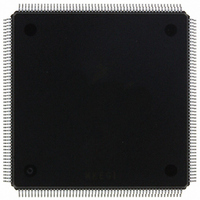
MCF5407AI220 Freescale Semiconductor, MCF5407AI220 Datasheet - Page 425

MCF5407AI220
Manufacturer Part Number
MCF5407AI220
Description
IC MPU 32B 220MHZ COLDF 208-FQFP
Manufacturer
Freescale Semiconductor
Series
MCF540xr
Specifications of MCF5407AI220
Core Processor
Coldfire V4
Core Size
32-Bit
Speed
220MHz
Connectivity
EBI/EMI, I²C, UART/USART
Peripherals
DMA, WDT
Number Of I /o
16
Program Memory Type
ROMless
Ram Size
4K x 8
Voltage - Supply (vcc/vdd)
1.65 V ~ 3.6 V
Oscillator Type
External
Operating Temperature
0°C ~ 70°C
Package / Case
208-FQFP
Maximum Clock Frequency
220 MHz
Operating Supply Voltage
1.8 V, 3.3 V
Maximum Operating Temperature
+ 105 C
Mounting Style
SMD/SMT
Minimum Operating Temperature
0 C
Program Memory Size
24KB
Cpu Speed
220MHz
Embedded Interface Type
I2C, UART
Digital Ic Case Style
FQFP
No. Of Pins
208
Supply Voltage Range
3.3V
Rohs Compliant
Yes
For Use With
M5407C3 - KIT EVAL FOR MCF5407 W/ETHERNET
Lead Free Status / RoHS Status
Lead free / RoHS Compliant
Eeprom Size
-
Program Memory Size
-
Data Converters
-
Lead Free Status / Rohs Status
Lead free / RoHS Compliant
Available stocks
Company
Part Number
Manufacturer
Quantity
Price
Company:
Part Number:
MCF5407AI220
Manufacturer:
freescaie
Quantity:
6
Company:
Part Number:
MCF5407AI220
Manufacturer:
Freescale Semiconductor
Quantity:
135
Company:
Part Number:
MCF5407AI220
Manufacturer:
FREESCALE
Quantity:
1 831
Company:
Part Number:
MCF5407AI220
Manufacturer:
Freescale Semiconductor
Quantity:
10 000
- Current page: 425 of 546
- Download datasheet (7Mb)
Timer Module Signals
17.9.2 Receiver Serial Data Input (RxD)
Data received on RxD is sampled on the rising edge of the clock source, with the lsb
received first. For UART1 in modem mode, data received on RxD is sampled on the falling
edge of the clock signal driving UART1’s CTS input. UART1 transfers can be specified as
either lsb or msb first.
17.9.3 Clear to Send (CTS)
This input can generate an interrupt on a change of state. For UART1 in modem mode, CTS
must be driven by the serial bit clock from the external CODEC or AC97 controller.
17.9.4 Request to Send (RTS)
This output can be programmed to be negated or asserted automatically by either the
receiver or the transmitter. When connected to a transmitter’s CTS, RTS can control serial
data flow. For UART1 in AC97 mode, RTS serves as the frame sync or start of frame (SOF),
output to the external AC97 controller. When this mode is used, the AC97 BIT_CLK, which
is input on CTS, is divided by 256.
17.10 Timer Module Signals
The signals in the following sections are external interfaces to the two general-purpose
MCF5407 timers. These 16-bit timers can capture timer values, trigger external events or
internal interrupts, or count external events.
17.10.1 Timer Inputs (TIN[1:0])
TIN[1:0] can be programmed as clocks that cause events in the counter and prescalers.
They can also cause captures on the rising edge, falling edge, or both edges.
17.10.2 Timer Outputs (TOUT1, TOUT0)
The programmable timer outputs (TOUT1 and TOUT0) pulse or toggle on various timer
events.
17.11 Parallel I/O Port (PP[15:0])
This 16-bit bus is dedicated for general-purpose I/O. The parallel port is multiplexed with
the A[31:24], TT[1:0], TM[2:0], TIP, and DREQ[1:0]. These 16 bits are programmed for
functionality with the PAR in the SIM.
The system designer controls the reset value of this register by driving D4 with a 1 or 0 on
the rising edge of RSTI (reset input to MCF5407 device). At reset, the system is configured
as PP[15:0] if D4 is 0; otherwise alternate pin functions selected by PAR = 1 are used.
Chapter 17. Signal Descriptions
17-19
Related parts for MCF5407AI220
Image
Part Number
Description
Manufacturer
Datasheet
Request
R
Part Number:
Description:
Mcf5407 Coldfire Integrated Microprocessor User
Manufacturer:
Freescale Semiconductor, Inc
Datasheet:
Part Number:
Description:
Manufacturer:
Freescale Semiconductor, Inc
Datasheet:
Part Number:
Description:
Manufacturer:
Freescale Semiconductor, Inc
Datasheet:
Part Number:
Description:
Manufacturer:
Freescale Semiconductor, Inc
Datasheet:
Part Number:
Description:
Manufacturer:
Freescale Semiconductor, Inc
Datasheet:
Part Number:
Description:
Manufacturer:
Freescale Semiconductor, Inc
Datasheet:
Part Number:
Description:
Manufacturer:
Freescale Semiconductor, Inc
Datasheet:
Part Number:
Description:
Manufacturer:
Freescale Semiconductor, Inc
Datasheet:
Part Number:
Description:
Manufacturer:
Freescale Semiconductor, Inc
Datasheet:
Part Number:
Description:
Manufacturer:
Freescale Semiconductor, Inc
Datasheet:
Part Number:
Description:
Manufacturer:
Freescale Semiconductor, Inc
Datasheet:
Part Number:
Description:
Manufacturer:
Freescale Semiconductor, Inc
Datasheet:
Part Number:
Description:
Manufacturer:
Freescale Semiconductor, Inc
Datasheet:
Part Number:
Description:
Manufacturer:
Freescale Semiconductor, Inc
Datasheet:
Part Number:
Description:
Manufacturer:
Freescale Semiconductor, Inc
Datasheet:


