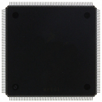
MCF5407AI220 Freescale Semiconductor, MCF5407AI220 Datasheet - Page 233

MCF5407AI220
Manufacturer Part Number
MCF5407AI220
Description
IC MPU 32B 220MHZ COLDF 208-FQFP
Manufacturer
Freescale Semiconductor
Series
MCF540xr
Specifications of MCF5407AI220
Core Processor
Coldfire V4
Core Size
32-Bit
Speed
220MHz
Connectivity
EBI/EMI, I²C, UART/USART
Peripherals
DMA, WDT
Number Of I /o
16
Program Memory Type
ROMless
Ram Size
4K x 8
Voltage - Supply (vcc/vdd)
1.65 V ~ 3.6 V
Oscillator Type
External
Operating Temperature
0°C ~ 70°C
Package / Case
208-FQFP
Maximum Clock Frequency
220 MHz
Operating Supply Voltage
1.8 V, 3.3 V
Maximum Operating Temperature
+ 105 C
Mounting Style
SMD/SMT
Minimum Operating Temperature
0 C
Program Memory Size
24KB
Cpu Speed
220MHz
Embedded Interface Type
I2C, UART
Digital Ic Case Style
FQFP
No. Of Pins
208
Supply Voltage Range
3.3V
Rohs Compliant
Yes
For Use With
M5407C3 - KIT EVAL FOR MCF5407 W/ETHERNET
Lead Free Status / RoHS Status
Lead free / RoHS Compliant
Eeprom Size
-
Program Memory Size
-
Data Converters
-
Lead Free Status / Rohs Status
Lead free / RoHS Compliant
Available stocks
Company
Part Number
Manufacturer
Quantity
Price
Company:
Part Number:
MCF5407AI220
Manufacturer:
freescaie
Quantity:
6
Company:
Part Number:
MCF5407AI220
Manufacturer:
Freescale Semiconductor
Quantity:
135
Company:
Part Number:
MCF5407AI220
Manufacturer:
FREESCALE
Quantity:
1 831
Company:
Part Number:
MCF5407AI220
Manufacturer:
Freescale Semiconductor
Quantity:
10 000
- Current page: 233 of 546
- Download datasheet (7Mb)
multiplied up as determined by the logic level of the multiplexed D[2:0]/DIVIDE[2:0] pins
during reset to create PCLK.
7.2.3 Reduced-Power Mode
The PCLK can be turned off in a predictable manner to conserve system power. To allow
fast restart of the MCF5407 processor core, the PLL continues to operate at the frequency
configured at reset. PCLK is disabled using the CPU STOP instruction and resumes normal
operation on interrupt, as described in Section 7.2.4, “PLL Control Register (PLLCR).”
7.2.4 PLL Control Register (PLLCR)
The PLL control register (PLLCR), Figure 7-2, provides control over the PLL.
Table 7-2 describes PLLCR bits.
6–4
2–0
Bit
7
3
Address
Reset
DISBCLKO BCLKO disable. Determines whether BCLKO is driven.
ENBSTOP
Field ENBSTOP
R/W
PLLIPL
Name
—
7
Enable CPU STOP instruction. Must be set for the ColdFire CPU STOP instruction to be
acknowledged. Cleared at reset and must be subsequently set for the processor to enter
low-power modes. Only clocks to the core are turned off because of the CPU STOP instruction.
Internal modules remain clocked and can generate interrupts to restart the ColdFire core.
0 Disable CPU STOP
1 Enable CPU STOP; STOP instruction turns off clocks to the ColdFire core.
PLL interrupt priority level to wake up from CPU STOP. Determines the minimum level an
interrupt (decoded as an interrupt priority level) must be to waken the PLL. The PLL then turns
clocks back on to the core processor and interrupt exception processing occurs.
000 Any interrupts can wake core
001 Interrupts 2–7
010 Interrupts 3–7
011 Interrupts 4–7
100 Interrupts 5–7
101 Interrupts 6–7
110 Interrupt 7 only
111 No interrupts can wake core. Any reset, including a watchdog reset, can wake the core.
No PLL phase lock time is required.
0 BCLKO is driven.
1 BCLKO is three-stated. BCLKO can be reenabled only by a reset.
Reserved, should be cleared.
Figure 7-2. PLL Control Register (PLLCR)
6
Table 7-2. PLLCR Field Descriptions
Chapter 7. Phase-Locked Loop (PLL)
PLLIPL
5
MBAR + 0x08
4
0000_0000
R/W
Description
DISBCLKO
3
2
—
1
PLL Operation
0
7-3
Related parts for MCF5407AI220
Image
Part Number
Description
Manufacturer
Datasheet
Request
R
Part Number:
Description:
Mcf5407 Coldfire Integrated Microprocessor User
Manufacturer:
Freescale Semiconductor, Inc
Datasheet:
Part Number:
Description:
Manufacturer:
Freescale Semiconductor, Inc
Datasheet:
Part Number:
Description:
Manufacturer:
Freescale Semiconductor, Inc
Datasheet:
Part Number:
Description:
Manufacturer:
Freescale Semiconductor, Inc
Datasheet:
Part Number:
Description:
Manufacturer:
Freescale Semiconductor, Inc
Datasheet:
Part Number:
Description:
Manufacturer:
Freescale Semiconductor, Inc
Datasheet:
Part Number:
Description:
Manufacturer:
Freescale Semiconductor, Inc
Datasheet:
Part Number:
Description:
Manufacturer:
Freescale Semiconductor, Inc
Datasheet:
Part Number:
Description:
Manufacturer:
Freescale Semiconductor, Inc
Datasheet:
Part Number:
Description:
Manufacturer:
Freescale Semiconductor, Inc
Datasheet:
Part Number:
Description:
Manufacturer:
Freescale Semiconductor, Inc
Datasheet:
Part Number:
Description:
Manufacturer:
Freescale Semiconductor, Inc
Datasheet:
Part Number:
Description:
Manufacturer:
Freescale Semiconductor, Inc
Datasheet:
Part Number:
Description:
Manufacturer:
Freescale Semiconductor, Inc
Datasheet:
Part Number:
Description:
Manufacturer:
Freescale Semiconductor, Inc
Datasheet:


