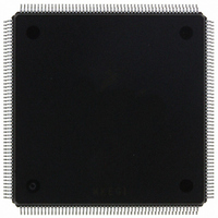
MCF5407AI220 Freescale Semiconductor, MCF5407AI220 Datasheet - Page 175

MCF5407AI220
Manufacturer Part Number
MCF5407AI220
Description
IC MPU 32B 220MHZ COLDF 208-FQFP
Manufacturer
Freescale Semiconductor
Series
MCF540xr
Specifications of MCF5407AI220
Core Processor
Coldfire V4
Core Size
32-Bit
Speed
220MHz
Connectivity
EBI/EMI, I²C, UART/USART
Peripherals
DMA, WDT
Number Of I /o
16
Program Memory Type
ROMless
Ram Size
4K x 8
Voltage - Supply (vcc/vdd)
1.65 V ~ 3.6 V
Oscillator Type
External
Operating Temperature
0°C ~ 70°C
Package / Case
208-FQFP
Maximum Clock Frequency
220 MHz
Operating Supply Voltage
1.8 V, 3.3 V
Maximum Operating Temperature
+ 105 C
Mounting Style
SMD/SMT
Minimum Operating Temperature
0 C
Program Memory Size
24KB
Cpu Speed
220MHz
Embedded Interface Type
I2C, UART
Digital Ic Case Style
FQFP
No. Of Pins
208
Supply Voltage Range
3.3V
Rohs Compliant
Yes
For Use With
M5407C3 - KIT EVAL FOR MCF5407 W/ETHERNET
Lead Free Status / RoHS Status
Lead free / RoHS Compliant
Eeprom Size
-
Program Memory Size
-
Data Converters
-
Lead Free Status / Rohs Status
Lead free / RoHS Compliant
Available stocks
Company
Part Number
Manufacturer
Quantity
Price
Company:
Part Number:
MCF5407AI220
Manufacturer:
freescaie
Quantity:
6
Company:
Part Number:
MCF5407AI220
Manufacturer:
Freescale Semiconductor
Quantity:
135
Company:
Part Number:
MCF5407AI220
Manufacturer:
FREESCALE
Quantity:
1 831
Company:
Part Number:
MCF5407AI220
Manufacturer:
Freescale Semiconductor
Quantity:
10 000
- Current page: 175 of 546
- Download datasheet (7Mb)
5.4.8 Extended Trigger Definition Register (XTDR)
The XTDR configures the operation of the hardware breakpoint logic that corresponds with
the ABHR1/ABLR1/AATR1 and DBR1/DBMR1 registers within the debug module and,
in conjunction with the TDR and its associated debug registers, controls the actions taken
under the defined conditions. The breakpoint logic may be configured as a one- or two-level
trigger, where TDR[31–16] and/or XTDR[31–16] define the second-level trigger and bits
15–0 define the first-level trigger. The XTDR is accessible in supervisor mode as debug
control register 0x17 using the WDEBUG instruction and via the BDM port using the
WDMREG
31–30
29/13
28–22
12–6
28/12
27/11
26/10
25/9
24/8
23/7
22/6
21/5
20–18/
4–2
20/4
19/3
18/2
17/1
16/0
Bits
TRC
EBL
EDx
DI
EAx
EPC
PCI
Name
command.
Trigger response control. Determines how the processor responds to a completed trigger condition.
The trigger response is always displayed on PSTDDATA.
00 Display on PSTDDATA only
01 Processor halt
10 Debug interrupt
11 Reserved
Enable breakpoint. Global enable for the breakpoint trigger. Setting TDR[EBL] or XTDR[EBL]
enables a breakpoint trigger; clearing both disables all breakpoints.
Setting an EDx bit enables the corresponding data breakpoint condition based on the size and
placement on the processor’s local data bus. Clearing all EDx bits disables data breakpoints.
EDLW
EDWL
EDWU Upper data word.
EDLL
EDLM
EDUM Upper middle data byte. Low-order byte of the high-order word.
EDUU
Data breakpoint invert. Provides a way to invert the logical sense of all the data breakpoint
comparators. This can develop a trigger based on the occurrence of a data value other than the
DBR contents.
Enable address bits. Setting an EA bit enables the corresponding address breakpoint. Clearing all
three bits disables the breakpoint.
EAI
EAR
EAL
Enable PC breakpoint. If set, this bit enables the PC breakpoint.
Breakpoint invert. If set, this bit allows execution outside a given region as defined by
PBR/PBR1/PBR2/PBR3 and PBMR to enable a trigger. If cleared, the PC breakpoint is defined
within the region defined by PBR/PBR1/PBR2/PBR3 and PBMR.
Data longword. Entire processor’s local data bus.
Lower data word.
Lower lower data byte. Low-order byte of the low-order word.
Lower middle data byte. High-order byte of the low-order word.
Upper upper data byte. High-order byte of the high-order word.
Enable address breakpoint inverted. Breakpoint is based outside the range between ABLR
and ABHR.
Enable address breakpoint range. The breakpoint is based on the inclusive range defined
by ABLR and ABHR.
Enable address breakpoint low. The breakpoint is based on the address in the ABLR.
Table 5-17. TDR Field Descriptions
Chapter 5. Debug Support
Description
Programming Model
5-19
Related parts for MCF5407AI220
Image
Part Number
Description
Manufacturer
Datasheet
Request
R
Part Number:
Description:
Mcf5407 Coldfire Integrated Microprocessor User
Manufacturer:
Freescale Semiconductor, Inc
Datasheet:
Part Number:
Description:
Manufacturer:
Freescale Semiconductor, Inc
Datasheet:
Part Number:
Description:
Manufacturer:
Freescale Semiconductor, Inc
Datasheet:
Part Number:
Description:
Manufacturer:
Freescale Semiconductor, Inc
Datasheet:
Part Number:
Description:
Manufacturer:
Freescale Semiconductor, Inc
Datasheet:
Part Number:
Description:
Manufacturer:
Freescale Semiconductor, Inc
Datasheet:
Part Number:
Description:
Manufacturer:
Freescale Semiconductor, Inc
Datasheet:
Part Number:
Description:
Manufacturer:
Freescale Semiconductor, Inc
Datasheet:
Part Number:
Description:
Manufacturer:
Freescale Semiconductor, Inc
Datasheet:
Part Number:
Description:
Manufacturer:
Freescale Semiconductor, Inc
Datasheet:
Part Number:
Description:
Manufacturer:
Freescale Semiconductor, Inc
Datasheet:
Part Number:
Description:
Manufacturer:
Freescale Semiconductor, Inc
Datasheet:
Part Number:
Description:
Manufacturer:
Freescale Semiconductor, Inc
Datasheet:
Part Number:
Description:
Manufacturer:
Freescale Semiconductor, Inc
Datasheet:
Part Number:
Description:
Manufacturer:
Freescale Semiconductor, Inc
Datasheet:


