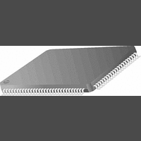
PC87393VJG National Semiconductor, PC87393VJG Datasheet - Page 19

PC87393VJG
Manufacturer Part Number
PC87393VJG
Description
IC, SUPER I/O DEVICE, TQFP-100
Manufacturer
National Semiconductor
Specifications of PC87393VJG
Data Rate
2Mbps
Supply Voltage Range
3V to 3.6V
Logic Case Style
TQFP
No. Of Pins
100
Operating Temperature Range
0°C to +70°C
Termination Type
SMD
Transceiver Type
Interface
Rohs Compliant
No
Available stocks
Company
Part Number
Manufacturer
Quantity
Price
Part Number:
PC87393VJG
Manufacturer:
NS/国半
Quantity:
20 000
- Current page: 19 of 148
- Download datasheet (703Kb)
1.0 Signal/Pin Connection and Description
1.5.4
DENSEL
DIR
DR1
DR0
DRATE0
DRATE1
DSKCHG
HDSEL
INDEX
MSEN1, 0
MTR1
MTR0
RDATA
STEP
TRK0
WDATA
WGATE
WP
Signal
Floppy Disk Controller (FDC)
33, 53
29, 49
41, 71,
72
30
34, 73
53
21, 45
22, 51
32, 52
42, 44
84, 73,
40
31
23, 46
28, 47
25, 50
27, 37
26, 36
24, 48
Pin(s)
I/O Buffer Type Power Well
O
O
O
O
O
O
O
O
O
O
I
I
I
I
I
I
OD
OD
OD
OD
OD
OD
OD
O
12
12
12
12
12
12
12
O
O
IN
IN
IN
IN
IN
IN
2/12
, O
, O
, O
, O
, O
, O
, O
3/6
3/6
T
T
T
T
T
T
2/12
2/12
2/12
2/12
2/12
2/12
2/12
V
V
V
V
V
V
V
V
V
V
V
V
V
V
V
V
DD
DD
DD
DD
DD
DD
DD
DD
DD
DD
DD
DD
DD
DD
DD
DD
Density Select. Indicates that a high FDC density data rate (500
Kbps, 1 Mbps or 2 Mbps) or a low density data rate (250 or 300
Kbps) is selected.
Direction. Determines the direction of the Floppy Disk Drive
(FDD) head movement (active = step in, inactive = step out)
during a seek operation.
Drive Select. Decoded output signals in 2-drive mode, or
encoded signals in 4-drive mode. Controlled by bits 1 and 0 of the
Digital Output register (DOR).
Data Rate 0. Reflects the value of bit 0 of the Configuration Control
register (CCR) or the Data Rate Select register (DSR), whichever
was written to last.
Data Rate 1. Reflects the value of bit 1 of the Configuration Control
register (CCR) or the Data Rate Select register (DSR), whichever
was written to last. Available on the PPM pins only.
Disk Change. Indicates if the drive door has been opened.
Head Select. Determines which side of the FDD is accessed.
Active low selects side 1, inactive selects side 0.
Index. Indicates the beginning of an FDD track.
Automatic Media Sense. Identifies the media type of the floppy
disk in drive 1 and 0, if the drive supports this protocol.
Motor Select. Active low, motor enable lines for drive 1 and 0,
controlled by bits D7-4 of the Digital Output register (DOR). MTR0 is
used to decode DR1 and DR0 in 4-drive mode.
Read Data. Raw serial input data stream read from the FDD.
Step. Issues pulses to the FDD at a software programmable rate
to move the head during a seek operation.
Track 0. Indicates to the controller that the head of the selected
FDD is at track 0.
Write Data. Carries out the pre-compensated serial data that is
written to the FDD. Pre-compensation is software selectable.
Write Gate. Enables the write circuitry of the selected FDD.
WGATE is designed to prevent glitches during power-up and
power-down. This prevents writing to the disk when power is
cycled.
Write Protected. Indicates that the disk in the selected drive is
write protected.
19
(Continued)
Description
www.national.com
Related parts for PC87393VJG
Image
Part Number
Description
Manufacturer
Datasheet
Request
R
Part Number:
Description:
National Semiconductor [8-Bit D/A Converter]
Manufacturer:
National Semiconductor
Datasheet:
Part Number:
Description:
National Semiconductor [Media Coprocessor]
Manufacturer:
National Semiconductor
Datasheet:
Part Number:
Description:
Digitally Controlled Tone and Volume Circuit with Stereo Audio Power Amplifier, Microphone Preamp Stage and National 3D Sound
Manufacturer:
National Semiconductor
Datasheet:
Part Number:
Description:
Digitally Controlled Tone and Volume Circuit with Stereo Audio Power Amplifier, Microphone Preamp Stage and National 3D Sound
Manufacturer:
National Semiconductor
Datasheet:
Part Number:
Description:
AC97 Rev 2 Codec with Sample Rate Conversion and National 3D Sound
Manufacturer:
National Semiconductor
Part Number:
Description:
Manufacturer:
National Semiconductor
Datasheet:
Part Number:
Description:
Manufacturer:
National Semiconductor
Datasheet:
Part Number:
Description:
General Purpose, Low Voltage, Low Power, Rail-to-Rail Output Operational Amplifiers
Manufacturer:
National Semiconductor
Datasheet:
Part Number:
Description:
8-bit 20 MSPS flash A/D converter.
Manufacturer:
National Semiconductor
Datasheet:
Part Number:
Description:
Low Noise Quad Operational Amplifier
Manufacturer:
National Semiconductor
Datasheet:
Part Number:
Description:
Quad Differential Line Receivers
Manufacturer:
National Semiconductor
Datasheet:
Part Number:
Description:
Quad High Speed Trapezoidal? Bus Transceiver
Manufacturer:
National Semiconductor
Datasheet:
Part Number:
Description:
Dual Line Receiver
Manufacturer:
National Semiconductor
Datasheet:
Part Number:
Description:
TTL to 10k ECL Level Translator with Latch
Manufacturer:
National Semiconductor
Datasheet:


