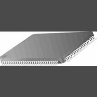
PC87393VJG National Semiconductor, PC87393VJG Datasheet - Page 22

PC87393VJG
Manufacturer Part Number
PC87393VJG
Description
IC, SUPER I/O DEVICE, TQFP-100
Manufacturer
National Semiconductor
Specifications of PC87393VJG
Data Rate
2Mbps
Supply Voltage Range
3V to 3.6V
Logic Case Style
TQFP
No. Of Pins
100
Operating Temperature Range
0°C to +70°C
Termination Type
SMD
Transceiver Type
Interface
Rohs Compliant
No
Available stocks
Company
Part Number
Manufacturer
Quantity
Price
Part Number:
PC87393VJG
Manufacturer:
NS/国半
Quantity:
20 000
- Current page: 22 of 148
- Download datasheet (703Kb)
www.national.com
1.0 Signal/Pin Connection and Description
1.5.10 Serial Port 1 and Serial Port 2 (SP1 and SP2)
CTS1
CTS2
DCD1
DCD2
DSR1
DSR2
DTR1_
BOUT1
DTR2_
BOUT2
RI1
RI2
RTS1
RTS2
SIN1
SIN2
SOUT1
SOUT2
Signal
60
79
55
74
56
75
61
80
62
81
58
77
57
76
59
78
Pin/s
I/O Buffer Type Power Well
O
O
O
I
I
I
I
I
IN
IN
IN
IN
IN
O
O
O
3/6
3/6
3/6
TS
TS
TS
TS
TS
V
V
V
V
V
V
V
V
DD
DD
DD
DD
DD
DD
DD
DD
Clear to Send. When low, indicate that the modem or other data
transfer device is ready to exchange data.
Data Carrier Detected. When low, indicate that the modem or
other data transfer device has detected the data carrier.
Data Set Ready. When low, indicate that the data transfer device,
e.g., modem, is ready to establish a communications link.
Data Terminal Ready. When low, indicate to the modem or other
data transfer device that the UART is ready to establish a
communications link. After a system reset, these pins provide the
DTR function and set these signals to inactive high. Loopback
operation holds them inactive.
Baud Output. Provides the associated serial channel baud rate
generator output signal if test mode is selected, i.e., bit 7 of the
EXCR1 register is set.
DTR1_BOUT1 is used also as BADDR.
Ring Indicator. When low, indicate that a telephone ring signal
has been received by the modem. They are monitored during
power-off for wake-up event detection.
Request to Send. When low, indicate to the modem or other data
transfer device that the corresponding UART is ready to exchange
data. A system reset sets these signals to inactive high, and
loopback operation holds them inactive.
RTS1 is used also as TEST.
Serial Input. Receive composite serial data from the
communications link (peripheral device, modem or other data
transfer device).
Serial Output. Send composite serial data to the communications
link (peripheral device, modem or other data transfer device).
These signals are set active high after a system reset.
22
(Continued)
Description
Related parts for PC87393VJG
Image
Part Number
Description
Manufacturer
Datasheet
Request
R
Part Number:
Description:
National Semiconductor [8-Bit D/A Converter]
Manufacturer:
National Semiconductor
Datasheet:
Part Number:
Description:
National Semiconductor [Media Coprocessor]
Manufacturer:
National Semiconductor
Datasheet:
Part Number:
Description:
Digitally Controlled Tone and Volume Circuit with Stereo Audio Power Amplifier, Microphone Preamp Stage and National 3D Sound
Manufacturer:
National Semiconductor
Datasheet:
Part Number:
Description:
Digitally Controlled Tone and Volume Circuit with Stereo Audio Power Amplifier, Microphone Preamp Stage and National 3D Sound
Manufacturer:
National Semiconductor
Datasheet:
Part Number:
Description:
AC97 Rev 2 Codec with Sample Rate Conversion and National 3D Sound
Manufacturer:
National Semiconductor
Part Number:
Description:
Manufacturer:
National Semiconductor
Datasheet:
Part Number:
Description:
Manufacturer:
National Semiconductor
Datasheet:
Part Number:
Description:
General Purpose, Low Voltage, Low Power, Rail-to-Rail Output Operational Amplifiers
Manufacturer:
National Semiconductor
Datasheet:
Part Number:
Description:
8-bit 20 MSPS flash A/D converter.
Manufacturer:
National Semiconductor
Datasheet:
Part Number:
Description:
Low Noise Quad Operational Amplifier
Manufacturer:
National Semiconductor
Datasheet:
Part Number:
Description:
Quad Differential Line Receivers
Manufacturer:
National Semiconductor
Datasheet:
Part Number:
Description:
Quad High Speed Trapezoidal? Bus Transceiver
Manufacturer:
National Semiconductor
Datasheet:
Part Number:
Description:
Dual Line Receiver
Manufacturer:
National Semiconductor
Datasheet:
Part Number:
Description:
TTL to 10k ECL Level Translator with Latch
Manufacturer:
National Semiconductor
Datasheet:


