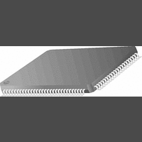
PC87393VJG National Semiconductor, PC87393VJG Datasheet - Page 30

PC87393VJG
Manufacturer Part Number
PC87393VJG
Description
IC, SUPER I/O DEVICE, TQFP-100
Manufacturer
National Semiconductor
Specifications of PC87393VJG
Data Rate
2Mbps
Supply Voltage Range
3V to 3.6V
Logic Case Style
TQFP
No. Of Pins
100
Operating Temperature Range
0°C to +70°C
Termination Type
SMD
Transceiver Type
Interface
Rohs Compliant
No
Available stocks
Company
Part Number
Manufacturer
Quantity
Price
Part Number:
PC87393VJG
Manufacturer:
NS/国半
Quantity:
20 000
- Current page: 30 of 148
- Download datasheet (703Kb)
www.national.com
2.0 Device Architecture and Configuration
F0h-FEh
Index
Index
Index
70h
71h
74h
75h
Interrupt Request
Interrupt Number
and Wake-Up on
Register Name
Register Name
Register Name
Logical Device
DMA Channel
DMA Channel
Configuration
IRQ Enable
Type Select
Select 0
Select 1
Table 12. Special Logical Device Configuration Registers
Indicates selected interrupt number.
Bits 7-5 - Reserved.
Bit 4 - Enables wake-up on the IRQ of the logical device. When enabled, IRQ
assertion triggers a wake-up event.
Bits 3–0 select the interrupt number. A value of 1 selects IRQL1. A value of 15
selects IRQL15. IRQL0 is not a valid interrupt selection and represents no interrupt
selection.
Indicates the type and level of the interrupt request number selected in the previous
register.
If a logical device supports only one type of interrupt, this register is read only.
Bits 7–2 - Reserved.
Bit 0 - Type of interrupt request selected in the previous register.
Bit 1 - Level of the interrupt request selected in the previous register.
Indicates selected DMA channel for DMA 0 of the logical device (0 - The first DMA
channel in case of using more than one DMA channel).
Bits 7-3 - Reserved.
Bits 2-0 select the DMA channel for DMA 0. The valid choices are 0-3, where a
value of 0 selects DMA channel 0, 1 selects channel 1, etc.
Indicates selected DMA channel for DMA 1 of the logical device (1 - The second
DMA channel in case of using more than one DMA channel).
Bits 7-3 - Reserved.
Bits 2-0 select the DMA channel for DMA 1. The valid choices are 0-3, where a
value of 0 selects DMA channel 0, 1 selects channel 1, etc.
Special (vendor-defined) configuration options
Table 10. Interrupt Configuration Registers
0: Disabled (default)
1: Enabled
0: Edge
1: Level
0: Low polarity
1: High polarity
A value of 4 indicates that no DMA channel is active.
The values 5-7 are reserved.
A value of 4 indicates that no DMA channel is active.
The values 5-7 are reserved.
Table 11. DMA Configuration Registers
30
(Continued)
Description
Description
Description
Related parts for PC87393VJG
Image
Part Number
Description
Manufacturer
Datasheet
Request
R
Part Number:
Description:
National Semiconductor [8-Bit D/A Converter]
Manufacturer:
National Semiconductor
Datasheet:
Part Number:
Description:
National Semiconductor [Media Coprocessor]
Manufacturer:
National Semiconductor
Datasheet:
Part Number:
Description:
Digitally Controlled Tone and Volume Circuit with Stereo Audio Power Amplifier, Microphone Preamp Stage and National 3D Sound
Manufacturer:
National Semiconductor
Datasheet:
Part Number:
Description:
Digitally Controlled Tone and Volume Circuit with Stereo Audio Power Amplifier, Microphone Preamp Stage and National 3D Sound
Manufacturer:
National Semiconductor
Datasheet:
Part Number:
Description:
AC97 Rev 2 Codec with Sample Rate Conversion and National 3D Sound
Manufacturer:
National Semiconductor
Part Number:
Description:
Manufacturer:
National Semiconductor
Datasheet:
Part Number:
Description:
Manufacturer:
National Semiconductor
Datasheet:
Part Number:
Description:
General Purpose, Low Voltage, Low Power, Rail-to-Rail Output Operational Amplifiers
Manufacturer:
National Semiconductor
Datasheet:
Part Number:
Description:
8-bit 20 MSPS flash A/D converter.
Manufacturer:
National Semiconductor
Datasheet:
Part Number:
Description:
Low Noise Quad Operational Amplifier
Manufacturer:
National Semiconductor
Datasheet:
Part Number:
Description:
Quad Differential Line Receivers
Manufacturer:
National Semiconductor
Datasheet:
Part Number:
Description:
Quad High Speed Trapezoidal? Bus Transceiver
Manufacturer:
National Semiconductor
Datasheet:
Part Number:
Description:
Dual Line Receiver
Manufacturer:
National Semiconductor
Datasheet:
Part Number:
Description:
TTL to 10k ECL Level Translator with Latch
Manufacturer:
National Semiconductor
Datasheet:


