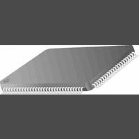
PC87393VJG National Semiconductor, PC87393VJG Datasheet - Page 98

PC87393VJG
Manufacturer Part Number
PC87393VJG
Description
IC, SUPER I/O DEVICE, TQFP-100
Manufacturer
National Semiconductor
Specifications of PC87393VJG
Data Rate
2Mbps
Supply Voltage Range
3V to 3.6V
Logic Case Style
TQFP
No. Of Pins
100
Operating Temperature Range
0°C to +70°C
Termination Type
SMD
Transceiver Type
Interface
Rohs Compliant
No
Available stocks
Company
Part Number
Manufacturer
Quantity
Price
Part Number:
PC87393VJG
Manufacturer:
NS/国半
Quantity:
20 000
www.national.com
6.0 Musical Instrument Digital Interface (MIDI) Port
6.2.5
The MIDI Signals Routing Control Logic controls the various routing options available for the MIDI transmit and receive sig-
nals. It is controlled by the MIDI Control register (MCNTL, see Section 6.3.6). These routing options are not part of the Leg-
acy definition of the MIDI Port.
6.2.6
The MIDI Port can be operated in one of the following modes:
Pass-Thru (Non-UART) Mode
After a hardware reset, the MIDI Port is in Pass-Thru mode.
In this mode, transmission is disabled by default, and all writes to the MIDI Data Out register (MDO, see Section 6.3.3) are
ignored. Transmission in this mode may be enabled by setting bit 4 of the MIDI Control register (MCNTL, see Section 6.3.6).
Receive in Pass-Thru mode is enabled, and a 16-byte Receive FIFO is available. Reading the MIDI Data In register (MDI,
see Section 6.3.2) in this mode returns the oldest data stored in the Receive FIFO. If serial data is received while the Receive
FIFO is full with data that has not yet been read, the last received data is lost, thus maintaining the data that was previously
stored in the Receive Buffer.
When in Pass-Thru mode, the MIDI Port responds to commands issued by the host, as follows:
Putting the acknowledge byte of FEh is equivalent to receiving a data byte. Therefore, once an acknowledge byte is put in
the Receive Buffer, it causes the Receive Buffer Empty status flag (see Section 6.2.7) to be cleared, which may also cause
a MIDI Port interrupt request to be issued.
When the Receive FIFO is disabled, switching from Pass-Thru mode to UART mode causes data stored in the Receive Buff-
er to be lost. After switching to UART mode, the MIDI Port is blocked for receive until the acknowledge byte is read from the
Receive Buffer.
If a command is issued to the MIDI Port while the MIDI Communication Engine is in the middle of a byte transfer (the Start
bit has been transmitted or received), the execution of the command and the response are postponed until the ongoing byte
transfer is completed.
After each MIDI Port operation in Pass-Thru mode, the MIDI Status register (MSTAT, see Section 6.3.4) is updated accord-
ingly.
Pass-Thru (Non-UART) Mode (default)
UART Mode.
3Fh puts the MIDI Port in UART mode. Also, in response to this command, the MIDI Port puts an acknowledge byte
of FEh in the Receive Buffer.
A0h-A7h or ABh causes the MIDI Port to put an acknowledge byte of FEh followed by a data byte of 00h in the Re-
ceive Buffer.
ACh causes the MIDI Port to put an acknowledge byte of FEh, followed by a data byte of 15h, in the Receive Buffer.
ADh causes the MIDI Port to put an acknowledge byte of FEh, followed by a data byte of 01h, in the Receive Buffer.
AFh causes the MIDI Port to put an acknowledge byte of FEh, followed by a data byte of 64h, in the Receive Buffer.
FFh resets the MIDI Port to its initial state, including all the bits of the MSTAT register. In response, the MIDI Port
puts an acknowledge of FEh in the Receive Buffer. This command is usually referred to as the MIDI Reset Command.
The MIDI Port responds to all other commands by putting an acknowledge byte of FEh in the Receive Buffer.
MIDI Signals Routing Control Logic
Operation Modes
MIDI Signal
Data Bits
Start
Bit
Figure 19. MIDI Byte Transfer Waveform
LSB
1
0
32 sec
1
98
0
1
(Continued)
0
1
MSB
0
Stop
Bit


