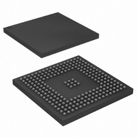
AT91SAM9RL64-CU Atmel, AT91SAM9RL64-CU Datasheet - Page 573

AT91SAM9RL64-CU
Manufacturer Part Number
AT91SAM9RL64-CU
Description
IC ARM9 MCU 217-LFBGA
Manufacturer
Atmel
Series
AT91SAMr
Specifications of AT91SAM9RL64-CU
Core Processor
ARM9
Core Size
16/32-Bit
Speed
240MHz
Connectivity
EBI/EMI, I²C, MMC, SPI, SSC, UART/USART, USB
Peripherals
AC'97, LCD, POR, PWM, WDT
Number Of I /o
118
Program Memory Size
32KB (32K x 8)
Program Memory Type
ROM
Ram Size
72K x 8
Voltage - Supply (vcc/vdd)
1.08 V ~ 1.32 V
Data Converters
A/D 6x10b
Oscillator Type
Internal
Operating Temperature
-40°C ~ 85°C
Package / Case
217-LFBGA
Processor Series
AT91SAMx
Core
ARM926EJ-S
Data Bus Width
32 bit
Data Ram Size
64 KB
Interface Type
2-Wire, SPI, SSC, USART
Maximum Clock Frequency
240 MHz
Number Of Programmable I/os
118
Number Of Timers
4
Maximum Operating Temperature
+ 85 C
Mounting Style
SMD/SMT
3rd Party Development Tools
JTRACE-ARM-2M, MDK-ARM, RL-ARM, ULINK2
Development Tools By Supplier
AT91SAM-ICE, AT91-ISP
Minimum Operating Temperature
- 40 C
On-chip Adc
10 bit, 6 Channel
Controller Family/series
AT91SAM9xxx
No. Of I/o's
118
Ram Memory Size
64KB
Cpu Speed
240MHz
No. Of Timers
1
Rohs Compliant
Yes
Package
217LFBGA
Device Core
ARM926EJ-S
Family Name
91S
Maximum Speed
240 MHz
Operating Supply Voltage
1.8|3.3 V
For Use With
AT91SAM9RL-EK - KIT EVAL FOR AT91SAM9RLAT91SAM-ICE - EMULATOR FOR AT91 ARM7/ARM9
Lead Free Status / RoHS Status
Lead free / RoHS Compliant
Eeprom Size
-
Lead Free Status / Rohs Status
Lead free / RoHS Compliant
Available stocks
Company
Part Number
Manufacturer
Quantity
Price
Company:
Part Number:
AT91SAM9RL64-CU
Manufacturer:
ATMEL
Quantity:
16
Company:
Part Number:
AT91SAM9RL64-CU
Manufacturer:
ATMEL
Quantity:
255
Part Number:
AT91SAM9RL64-CU
Manufacturer:
ATMEGL
Quantity:
20 000
- Current page: 573 of 903
- Download datasheet (13Mb)
37.3.3
37.3.3.1
37.3.3.2
6289C–ATARM–28-May-09
DMAC Transfer Types
Multi-buffer Transfers
Buffer Chaining Using Linked Lists
shaking interface is to allow the DMAC to attempt AMBA transfers to the peripheral once the
channel is enabled. If the peripheral slave cannot accept these AMBA transfers, it inserts wait
states onto the bus until it is ready; it is not recommended that more than 16 wait states be
inserted onto the bus.
A DMAC transfer may consist of single or multi-buffers transfers. On successive buffers of a
multi-buffer transfer, the DMAC_SADDRx/DMAC_DADDRx registers in the DMAC are repro-
grammed using either of the following methods:
On successive buffers of a multi-buffer transfer, the DMAC_CTRLAx and DMAC_CTRLBx regis-
ters in the DMAC are re-programmed using either of the following methods:
When buffer chaining, using linked lists is the multi-buffer method of choice, and on successive
buffers, the DMAC_DSCRx register in the DMAC is re-programmed using the following method:
A buffer descriptor (LLI) consists of following registers, DMAC_SADDRx, DMAC_DADDRx,
DMAC_DSCRx, DMAC_CTRLAx, DMAC_CTRLBx.These registers, along with the
DMAC_CFGx register, are used by the DMAC to set up and describe the buffer transfer.
In this case, the DMAC re-programs the channel registers prior to the start of each buffer by
fetching the buffer descriptor for that buffer from system memory. This is known as an LLI
update.
DMAC buffer chaining is supported by using a Descriptor Pointer register (DMAC_DSCRx) that
stores the address in memory of the next buffer descriptor. Each buffer descriptor contains the
corresponding buffer descriptor (DMAC_SADDRx, DMAC_DADDRx, DMAC_DSCRx,
DMAC_CTRLAx DMAC_CTRLBx).
To set up buffer chaining, a sequence of linked lists must be programmed in memory.
The DMAC_SADDRx, DMAC_DADDRx, DMAC_DSCRx, DMAC_CTRLAx and DMAC_CTRLBx
registers are fetched from system memory on an LLI update. The updated content of the
DMAC_CTRLAx register is written back to memory on buffer completion.
574
chaining.
The Linked List multi-buffer transfer is initiated by programming DMAC_DSCRx with DSCRx(0)
(LLI(0) base address) and DMAC_CTRLBx register with both SRC_DSCR and DST_DSCR set
to 0. Other fields and registers are ignored and overwritten when the descriptor is retrieved from
memory.
The last transfer descriptor must be written to memory with its next descriptor address set to 0.
• Buffer chaining using linked lists
• Replay mode
• Contiguous address between buffers
• Buffer chaining using linked lists
• Replay mode
• Buffer chaining using linked lists
shows how to use chained linked lists in memory to define multi-buffer transfers using buffer
AT91SAM9R64/RL64 Preliminary
Figure 37-4 on page
573
Related parts for AT91SAM9RL64-CU
Image
Part Number
Description
Manufacturer
Datasheet
Request
R

Part Number:
Description:
MCU, MPU & DSP Development Tools KICKSTART KIT FOR AT91SAM9 PLUS
Manufacturer:
IAR Systems

Part Number:
Description:
DEV KIT FOR AVR/AVR32
Manufacturer:
Atmel
Datasheet:

Part Number:
Description:
INTERVAL AND WIPE/WASH WIPER CONTROL IC WITH DELAY
Manufacturer:
ATMEL Corporation
Datasheet:

Part Number:
Description:
Low-Voltage Voice-Switched IC for Hands-Free Operation
Manufacturer:
ATMEL Corporation
Datasheet:

Part Number:
Description:
MONOLITHIC INTEGRATED FEATUREPHONE CIRCUIT
Manufacturer:
ATMEL Corporation
Datasheet:

Part Number:
Description:
AM-FM Receiver IC U4255BM-M
Manufacturer:
ATMEL Corporation
Datasheet:

Part Number:
Description:
Monolithic Integrated Feature Phone Circuit
Manufacturer:
ATMEL Corporation
Datasheet:

Part Number:
Description:
Multistandard Video-IF and Quasi Parallel Sound Processing
Manufacturer:
ATMEL Corporation
Datasheet:

Part Number:
Description:
High-performance EE PLD
Manufacturer:
ATMEL Corporation
Datasheet:

Part Number:
Description:
8-bit Flash Microcontroller
Manufacturer:
ATMEL Corporation
Datasheet:

Part Number:
Description:
2-Wire Serial EEPROM
Manufacturer:
ATMEL Corporation
Datasheet:


