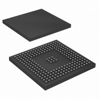
AT91SAM9RL64-CU Atmel, AT91SAM9RL64-CU Datasheet - Page 756

AT91SAM9RL64-CU
Manufacturer Part Number
AT91SAM9RL64-CU
Description
IC ARM9 MCU 217-LFBGA
Manufacturer
Atmel
Series
AT91SAMr
Specifications of AT91SAM9RL64-CU
Core Processor
ARM9
Core Size
16/32-Bit
Speed
240MHz
Connectivity
EBI/EMI, I²C, MMC, SPI, SSC, UART/USART, USB
Peripherals
AC'97, LCD, POR, PWM, WDT
Number Of I /o
118
Program Memory Size
32KB (32K x 8)
Program Memory Type
ROM
Ram Size
72K x 8
Voltage - Supply (vcc/vdd)
1.08 V ~ 1.32 V
Data Converters
A/D 6x10b
Oscillator Type
Internal
Operating Temperature
-40°C ~ 85°C
Package / Case
217-LFBGA
Processor Series
AT91SAMx
Core
ARM926EJ-S
Data Bus Width
32 bit
Data Ram Size
64 KB
Interface Type
2-Wire, SPI, SSC, USART
Maximum Clock Frequency
240 MHz
Number Of Programmable I/os
118
Number Of Timers
4
Maximum Operating Temperature
+ 85 C
Mounting Style
SMD/SMT
3rd Party Development Tools
JTRACE-ARM-2M, MDK-ARM, RL-ARM, ULINK2
Development Tools By Supplier
AT91SAM-ICE, AT91-ISP
Minimum Operating Temperature
- 40 C
On-chip Adc
10 bit, 6 Channel
Controller Family/series
AT91SAM9xxx
No. Of I/o's
118
Ram Memory Size
64KB
Cpu Speed
240MHz
No. Of Timers
1
Rohs Compliant
Yes
Package
217LFBGA
Device Core
ARM926EJ-S
Family Name
91S
Maximum Speed
240 MHz
Operating Supply Voltage
1.8|3.3 V
For Use With
AT91SAM9RL-EK - KIT EVAL FOR AT91SAM9RLAT91SAM-ICE - EMULATOR FOR AT91 ARM7/ARM9
Lead Free Status / RoHS Status
Lead free / RoHS Compliant
Eeprom Size
-
Lead Free Status / Rohs Status
Lead free / RoHS Compliant
Available stocks
Company
Part Number
Manufacturer
Quantity
Price
Company:
Part Number:
AT91SAM9RL64-CU
Manufacturer:
ATMEL
Quantity:
16
Company:
Part Number:
AT91SAM9RL64-CU
Manufacturer:
ATMEL
Quantity:
255
Part Number:
AT91SAM9RL64-CU
Manufacturer:
ATMEGL
Quantity:
20 000
- Current page: 756 of 903
- Download datasheet (13Mb)
41.4.12
41.4.12.1
Figure 41-18. UDPHS Device State Diagram
756
AT91SAM9R64/RL64 Preliminary
Power Modes
Controlling Device States
A USB device has several possible states. Refer to Chapter 9 (USB Device Framework) of the
Universal Serial Bus Specification, Rev 2.0.
Movement from one state to another depends on the USB bus state or on standard requests
sent through control transactions via the default endpoint (endpoint 0).
After a period of bus inactivity, the USB device enters Suspend Mode. Accepting Sus-
pend/Resume requests from the USB host is mandatory. Constraints in Suspend Mode are very
strict for bus-powered applications; devices may not consume more than 500 µA on the USB
bus.
While in Suspend Mode, the host may wake up a device by sending a resume signal (bus activ-
ity) or a USB device may send a wake-up request to the host, e.g., waking up a PC by moving a
USB mouse.
The wake-up feature is not mandatory for all devices and must be negotiated with the host.
Reset
Interruption
Power
Deconfigured
Deconfigured
Hub Reset
Device
or
Configured
Attached
Powered
Address
Default
Configured
Configured
Assigned
Address
Device
Hub
Reset
Bus Inactive
Bus Inactive
Bus Inactive
Bus Inactive
Bus Activity
Bus Activity
Bus Activity
Bus Activity
Suspended
Suspended
Suspended
Suspended
6289C–ATARM–28-May-09
Related parts for AT91SAM9RL64-CU
Image
Part Number
Description
Manufacturer
Datasheet
Request
R

Part Number:
Description:
MCU, MPU & DSP Development Tools KICKSTART KIT FOR AT91SAM9 PLUS
Manufacturer:
IAR Systems

Part Number:
Description:
DEV KIT FOR AVR/AVR32
Manufacturer:
Atmel
Datasheet:

Part Number:
Description:
INTERVAL AND WIPE/WASH WIPER CONTROL IC WITH DELAY
Manufacturer:
ATMEL Corporation
Datasheet:

Part Number:
Description:
Low-Voltage Voice-Switched IC for Hands-Free Operation
Manufacturer:
ATMEL Corporation
Datasheet:

Part Number:
Description:
MONOLITHIC INTEGRATED FEATUREPHONE CIRCUIT
Manufacturer:
ATMEL Corporation
Datasheet:

Part Number:
Description:
AM-FM Receiver IC U4255BM-M
Manufacturer:
ATMEL Corporation
Datasheet:

Part Number:
Description:
Monolithic Integrated Feature Phone Circuit
Manufacturer:
ATMEL Corporation
Datasheet:

Part Number:
Description:
Multistandard Video-IF and Quasi Parallel Sound Processing
Manufacturer:
ATMEL Corporation
Datasheet:

Part Number:
Description:
High-performance EE PLD
Manufacturer:
ATMEL Corporation
Datasheet:

Part Number:
Description:
8-bit Flash Microcontroller
Manufacturer:
ATMEL Corporation
Datasheet:

Part Number:
Description:
2-Wire Serial EEPROM
Manufacturer:
ATMEL Corporation
Datasheet:


