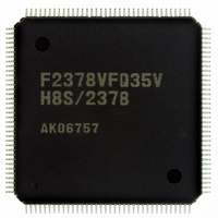
DF61657CN35FTV Renesas Electronics America, DF61657CN35FTV Datasheet - Page 23

DF61657CN35FTV
Manufacturer Part Number
DF61657CN35FTV
Description
IC H8SX/1657 MCU FLASH 120TQFP
Manufacturer
Renesas Electronics America
Series
H8® H8SX/1600r
Datasheet
1.DF61656N35FTV.pdf
(894 pages)
Specifications of DF61657CN35FTV
Core Processor
H8SX
Core Size
32-Bit
Speed
35MHz
Connectivity
SCI, SmartCard
Peripherals
DMA, PWM, WDT
Number Of I /o
82
Program Memory Size
768KB (768K x 8)
Program Memory Type
FLASH
Ram Size
24K x 8
Voltage - Supply (vcc/vdd)
3 V ~ 3.6 V
Data Converters
A/D 8x10b; D/A 2x8b
Oscillator Type
Internal
Operating Temperature
-20°C ~ 75°C
Package / Case
120-TQFP, 120-VQFP
For Use With
3DK1657 - DEV EVAL KIT FOR H8SX/1657
Lead Free Status / RoHS Status
Lead free / RoHS Compliant
Eeprom Size
-
Available stocks
Company
Part Number
Manufacturer
Quantity
Price
Company:
Part Number:
DF61657CN35FTV
Manufacturer:
RENESAS
Quantity:
101
Company:
Part Number:
DF61657CN35FTV
Manufacturer:
Renesas Electronics America
Quantity:
10 000
- Current page: 23 of 894
- Download datasheet (5Mb)
14.8 Interrupt Sources................................................................................................................ 618
14.9 Usage Notes ....................................................................................................................... 620
Section 15 A/D Converter..................................................................................625
15.1 Features.............................................................................................................................. 625
15.2 Input/Output Pins ............................................................................................................... 627
15.3 Register Descriptions ......................................................................................................... 627
15.4 Operation ........................................................................................................................... 632
15.5 Interrupt Source ................................................................................................................. 637
15.6 A/D Conversion Accuracy Definitions .............................................................................. 637
15.7 Usage Notes ....................................................................................................................... 639
Section 16 D/A Converter..................................................................................643
16.1 Features.............................................................................................................................. 643
16.2 Input/Output Pins ............................................................................................................... 644
14.7.8 Clock Output Control............................................................................................ 616
14.8.1 Interrupts in Normal Serial Communication Interface Mode ............................... 618
14.8.2 Interrupts in Smart Card Interface Mode .............................................................. 619
14.9.1 Module Stop State Setting .................................................................................... 620
14.9.2 Break Detection and Processing ........................................................................... 620
14.9.3 Mark State and Break Detection ........................................................................... 620
14.9.4 Receive Error Flags and Transmit Operations
14.9.5 Relation between Writing to TDR and TDRE Flag .............................................. 621
14.9.6 Restrictions on Using DMAC or DTC.................................................................. 621
14.9.7 Operations in Power-Down State.......................................................................... 622
15.3.1 A/D Data Registers A to H (ADDRA to ADDRH) .............................................. 628
15.3.2 A/D Control/Status Register (ADCSR) ................................................................ 629
15.3.3 A/D Control Register (ADCR) ............................................................................. 631
15.4.1 Single Mode.......................................................................................................... 632
15.4.2 Scan Mode ............................................................................................................ 633
15.4.3 Input Sampling and A/D Conversion Time .......................................................... 635
15.4.4 External Trigger Input Timing.............................................................................. 636
15.7.1 Module Stop State Setting .................................................................................... 639
15.7.2 Permissible Signal Source Impedance .................................................................. 639
15.7.3 Influences on Absolute Accuracy ......................................................................... 640
15.7.4 Setting Range of Analog Power Supply and Other Pins ....................................... 640
15.7.5 Notes on Board Design ......................................................................................... 640
15.7.6 Notes on Noise Countermeasures ......................................................................... 641
15.7.7 A/D Input Hold Function in Software Standby Mode .......................................... 642
(Clocked Synchronous Mode Only) ..................................................................... 620
Rev. 2.00 Jun. 28, 2007 Page xxi of xxiv
Related parts for DF61657CN35FTV
Image
Part Number
Description
Manufacturer
Datasheet
Request
R

Part Number:
Description:
KIT STARTER FOR M16C/29
Manufacturer:
Renesas Electronics America
Datasheet:

Part Number:
Description:
KIT STARTER FOR R8C/2D
Manufacturer:
Renesas Electronics America
Datasheet:

Part Number:
Description:
R0K33062P STARTER KIT
Manufacturer:
Renesas Electronics America
Datasheet:

Part Number:
Description:
KIT STARTER FOR R8C/23 E8A
Manufacturer:
Renesas Electronics America
Datasheet:

Part Number:
Description:
KIT STARTER FOR R8C/25
Manufacturer:
Renesas Electronics America
Datasheet:

Part Number:
Description:
KIT STARTER H8S2456 SHARPE DSPLY
Manufacturer:
Renesas Electronics America
Datasheet:

Part Number:
Description:
KIT STARTER FOR R8C38C
Manufacturer:
Renesas Electronics America
Datasheet:

Part Number:
Description:
KIT STARTER FOR R8C35C
Manufacturer:
Renesas Electronics America
Datasheet:

Part Number:
Description:
KIT STARTER FOR R8CL3AC+LCD APPS
Manufacturer:
Renesas Electronics America
Datasheet:

Part Number:
Description:
KIT STARTER FOR RX610
Manufacturer:
Renesas Electronics America
Datasheet:

Part Number:
Description:
KIT STARTER FOR R32C/118
Manufacturer:
Renesas Electronics America
Datasheet:

Part Number:
Description:
KIT DEV RSK-R8C/26-29
Manufacturer:
Renesas Electronics America
Datasheet:

Part Number:
Description:
KIT STARTER FOR SH7124
Manufacturer:
Renesas Electronics America
Datasheet:

Part Number:
Description:
KIT STARTER FOR H8SX/1622
Manufacturer:
Renesas Electronics America
Datasheet:

Part Number:
Description:
KIT DEV FOR SH7203
Manufacturer:
Renesas Electronics America
Datasheet:


