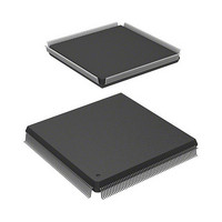
HD6417727F160V Renesas Electronics America, HD6417727F160V Datasheet - Page 43

HD6417727F160V
Manufacturer Part Number
HD6417727F160V
Description
MPU 3V 16K PB-FREE 240-QFP
Manufacturer
Renesas Electronics America
Series
SuperH® SH7700r
Datasheet
1.HD6417727BP100CV.pdf
(1098 pages)
Specifications of HD6417727F160V
Core Processor
SH-3 DSP
Core Size
32-Bit
Speed
160MHz
Connectivity
FIFO, SCI, SIO, SmartCard, USB
Peripherals
DMA, LCD, POR, WDT
Number Of I /o
104
Program Memory Type
ROMless
Ram Size
32K x 8
Voltage - Supply (vcc/vdd)
1.7 V ~ 2.05 V
Data Converters
A/D 6x10b; D/A 2x8b
Oscillator Type
Internal
Operating Temperature
-20°C ~ 75°C
Package / Case
240-QFP
Lead Free Status / RoHS Status
Lead free / RoHS Compliant
Eeprom Size
-
Program Memory Size
-
Available stocks
Company
Part Number
Manufacturer
Quantity
Price
Company:
Part Number:
HD6417727F160V
Manufacturer:
HITACHI
Quantity:
9
Company:
Part Number:
HD6417727F160V
Manufacturer:
Renesas Electronics America
Quantity:
10 000
Part Number:
HD6417727F160V
Manufacturer:
RENESAS/瑞萨
Quantity:
20 000
- Current page: 43 of 1098
- Download datasheet (7Mb)
Figure 14.19 Cycle-Steal Mode, Level input (CPU Access: 2 Cycles, DMA RD Access
Figure 14.20 Cycle-Steal Mode, Level input (CPU Access: 2 Cycles, DREQ Input Delayed)... 423
Figure 14.21 Cycle-Steal Mode, Edge input (CPU Access: 2 Cycles) ........................................ 424
Figure 14.22 Burst Mode, Level Input ........................................................................................ 425
Figure 14.23 Burst Mode, Edge Input ......................................................................................... 426
Figure 14.24 Source Address Reload Function Diagram ............................................................ 427
Figure 14.25 Timing Chart of Source Address Reload Function................................................. 428
Figure 14.26 CMT Block Diagram.............................................................................................. 431
Figure 14.27 Counter Operation .................................................................................................. 435
Figure 14.28 Count Timing ......................................................................................................... 436
Figure 14.29 Timing of CMF Setting .......................................................................................... 437
Figure 14.30 Timing of CMF Clear by the CPU ......................................................................... 437
Section 15 Timer (TMU)
Figure 15.1 TMU Block Diagram.............................................................................................. 444
Figure 15.2 Setting the Count Operation ................................................................................... 451
Figure 15.3 Auto-Reload Counter Operation............................................................................. 452
Figure 15.4 Count Timing when Internal Clock is Operating ................................................... 452
Figure 15.5 Count Timing when On-Chip RTC Clock is Operating ......................................... 453
Figure 15.6 UNF Set Timing ..................................................................................................... 453
Figure 15.7 Status Flag Clear Timing........................................................................................ 454
Section 16 Realtime Clock (RTC)
Figure 16.1 RTC Block Diagram............................................................................................... 458
Figure 16.2(a) Setting the Time ................................................................................................. 474
Figure 16.2(b) Setting the Time................................................................................................. 474
Figure 16.3 Reading the Time ................................................................................................... 475
Figure 16.4 Using the Alarm Function ...................................................................................... 476
Figure 16.5 Example of Crystal Oscillator Circuit Connection................................................. 477
Figure 16.6 Periodic Interrupt Function Setting ........................................................................ 478
Section 17 Serial Communication Interface (SCI)
Figure 17.1 SCI Block Diagram ................................................................................................ 482
Figure 17.2 SCPT[1]/SCK0 Pin ................................................................................................ 483
Figure 17.3 SCPT[0]/TxD0 Pin................................................................................................. 484
Figure 17.4 SCPT[0]/RxD0 Pin................................................................................................. 485
Figure 17.5 Data Format in Asynchronous Communication
Figure 17.6 Relationship between Output Clock and Transfer Data Phase
4 Cycles)................................................................................................................. 422
(Example with 8-Bit Data, Parity, Two Stop Bits)................................................. 511
(Asynchronous Mode)............................................................................................ 513
Rev.6.00 Mar. 27, 2009 Page xli of lvi
REJ09B0254-0600
Related parts for HD6417727F160V
Image
Part Number
Description
Manufacturer
Datasheet
Request
R

Part Number:
Description:
KIT STARTER FOR M16C/29
Manufacturer:
Renesas Electronics America
Datasheet:

Part Number:
Description:
KIT STARTER FOR R8C/2D
Manufacturer:
Renesas Electronics America
Datasheet:

Part Number:
Description:
R0K33062P STARTER KIT
Manufacturer:
Renesas Electronics America
Datasheet:

Part Number:
Description:
KIT STARTER FOR R8C/23 E8A
Manufacturer:
Renesas Electronics America
Datasheet:

Part Number:
Description:
KIT STARTER FOR R8C/25
Manufacturer:
Renesas Electronics America
Datasheet:

Part Number:
Description:
KIT STARTER H8S2456 SHARPE DSPLY
Manufacturer:
Renesas Electronics America
Datasheet:

Part Number:
Description:
KIT STARTER FOR R8C38C
Manufacturer:
Renesas Electronics America
Datasheet:

Part Number:
Description:
KIT STARTER FOR R8C35C
Manufacturer:
Renesas Electronics America
Datasheet:

Part Number:
Description:
KIT STARTER FOR R8CL3AC+LCD APPS
Manufacturer:
Renesas Electronics America
Datasheet:

Part Number:
Description:
KIT STARTER FOR RX610
Manufacturer:
Renesas Electronics America
Datasheet:

Part Number:
Description:
KIT STARTER FOR R32C/118
Manufacturer:
Renesas Electronics America
Datasheet:

Part Number:
Description:
KIT DEV RSK-R8C/26-29
Manufacturer:
Renesas Electronics America
Datasheet:

Part Number:
Description:
KIT STARTER FOR SH7124
Manufacturer:
Renesas Electronics America
Datasheet:

Part Number:
Description:
KIT STARTER FOR H8SX/1622
Manufacturer:
Renesas Electronics America
Datasheet:

Part Number:
Description:
KIT DEV FOR SH7203
Manufacturer:
Renesas Electronics America
Datasheet:


