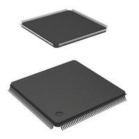
HD6417706F133 Renesas Electronics America, HD6417706F133 Datasheet - Page 40

HD6417706F133
Manufacturer Part Number
HD6417706F133
Description
IC SUPERH MPU ROMLESS 176LQFP
Manufacturer
Renesas Electronics America
Series
SuperH® SH7700r
Datasheet
1.HD6417706F133V.pdf
(751 pages)
Specifications of HD6417706F133
Core Processor
SH-3
Core Size
32-Bit
Speed
133MHz
Connectivity
EBI/EMI, FIFO, SCI, SmartCard
Peripherals
DMA, POR, WDT
Number Of I /o
103
Program Memory Type
ROMless
Ram Size
16K x 8
Voltage - Supply (vcc/vdd)
1.75 V ~ 2.05 V
Oscillator Type
Internal
Operating Temperature
-20°C ~ 75°C
Package / Case
176-LQFP
Lead Free Status / RoHS Status
Contains lead / RoHS non-compliant
Eeprom Size
-
Program Memory Size
-
Data Converters
-
Available stocks
Company
Part Number
Manufacturer
Quantity
Price
Part Number:
HD6417706F133
Manufacturer:
RENESAS/瑞萨
Quantity:
20 000
Company:
Part Number:
HD6417706F133V
Manufacturer:
EDISON
Quantity:
2 000
Company:
Part Number:
HD6417706F133V
Manufacturer:
Renesas Electronics America
Quantity:
10 000
Part Number:
HD6417706F133V
Manufacturer:
RENESAS/瑞萨
Quantity:
20 000
- Current page: 40 of 751
- Download datasheet (5Mb)
Figure 9.17
Figure 9.18
Figure 9.19
Figure 9.20
Figure 9.21
Figure 9.22
Figure 9.23
Figure 9.24
Figure 9.25
Figure 9.26
Figure 9.27
Figure 9.28
Figure 9.29
Figure 9.30
Section 10 Clock Pulse Generator (CPG)
Figure 10.1
Figure 10.2
Figure 10.3
Section 11 Watchdog Timer (WDT)
Figure 11.1
Figure 11.2
Section 12 Timer Unit (TMU)
Figure 12.1
Figure 12.2
Figure 12.3
Figure 12.4
Figure 12.5
Figure 12.6
Figure 12.7
Figure 12.8
Figure 12.9
Section 13 Realtime Clock (RTC)
Figure 13.1
Figure 13.2(a) Setting the Time................................................................................................... 357
Figure 13.2(b) Setting the Time................................................................................................... 357
Rev. 5.00 May 29, 2006 page xxxviii of xlviii
Cycle-Steal Mode, Level Input (CPU Access: 2 Cycles)..................................... 286
Cycle-Steal Mode, Level Input (CPU Access: 3 Cycles)..................................... 286
Cycle-Steal Mode, Level input
(CPU Access: 2 Cycles, DMA RD Access: 4 Cycles) ......................................... 286
Cycle-Steal Mode, Level input (CPU Access: 2 Cycles, DREQ Input Delayed) 287
Cycle-Steal Mode, Edge input (CPU Access: 2 Cycles)...................................... 287
Burst Mode, Level Input ...................................................................................... 287
Burst Mode, Edge Input....................................................................................... 288
Source Address Reload Function Diagram .......................................................... 288
Timing Chart of Source Address Reload Function .............................................. 289
CMT Block Diagram ........................................................................................... 292
Counter Operation................................................................................................ 295
Count Timing....................................................................................................... 296
CMF Set Timing .................................................................................................. 297
Timing of CMF Clear by the CPU....................................................................... 297
Block Diagram of Clock Pulse Generator............................................................ 304
Points for Attention when Using Crystal Oscillator............................................. 313
Points for Attention when Using PLL Oscillator Circuit ..................................... 314
Block Diagram of the WDT................................................................................. 315
Writing to WTCNT and WTCSR ........................................................................ 319
TMU Block Diagram ........................................................................................... 324
Setting the Count Operation................................................................................. 333
Auto-Reload Count Operation ............................................................................. 334
Count Timing when Internal Clock Is Operating................................................. 334
Count Timing when External Clock Is Operating (Both Edges Detected)........... 335
Count Timing when On-Chip RTC Clock Is Operating ...................................... 335
Operation Timing when Using the Input Capture Function
(Using TCLK Rising Edge) ................................................................................. 336
UNF Set Timing................................................................................................... 337
Status Flag Clear Timing ..................................................................................... 337
RTC Block Diagram ............................................................................................ 340
Related parts for HD6417706F133
Image
Part Number
Description
Manufacturer
Datasheet
Request
R

Part Number:
Description:
KIT STARTER FOR M16C/29
Manufacturer:
Renesas Electronics America
Datasheet:

Part Number:
Description:
KIT STARTER FOR R8C/2D
Manufacturer:
Renesas Electronics America
Datasheet:

Part Number:
Description:
R0K33062P STARTER KIT
Manufacturer:
Renesas Electronics America
Datasheet:

Part Number:
Description:
KIT STARTER FOR R8C/23 E8A
Manufacturer:
Renesas Electronics America
Datasheet:

Part Number:
Description:
KIT STARTER FOR R8C/25
Manufacturer:
Renesas Electronics America
Datasheet:

Part Number:
Description:
KIT STARTER H8S2456 SHARPE DSPLY
Manufacturer:
Renesas Electronics America
Datasheet:

Part Number:
Description:
KIT STARTER FOR R8C38C
Manufacturer:
Renesas Electronics America
Datasheet:

Part Number:
Description:
KIT STARTER FOR R8C35C
Manufacturer:
Renesas Electronics America
Datasheet:

Part Number:
Description:
KIT STARTER FOR R8CL3AC+LCD APPS
Manufacturer:
Renesas Electronics America
Datasheet:

Part Number:
Description:
KIT STARTER FOR RX610
Manufacturer:
Renesas Electronics America
Datasheet:

Part Number:
Description:
KIT STARTER FOR R32C/118
Manufacturer:
Renesas Electronics America
Datasheet:

Part Number:
Description:
KIT DEV RSK-R8C/26-29
Manufacturer:
Renesas Electronics America
Datasheet:

Part Number:
Description:
KIT STARTER FOR SH7124
Manufacturer:
Renesas Electronics America
Datasheet:

Part Number:
Description:
KIT STARTER FOR H8SX/1622
Manufacturer:
Renesas Electronics America
Datasheet:

Part Number:
Description:
KIT DEV FOR SH7203
Manufacturer:
Renesas Electronics America
Datasheet:


