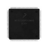
MC9S12XDP512MAG Freescale, MC9S12XDP512MAG Datasheet - Page 512

MC9S12XDP512MAG
Manufacturer Part Number
MC9S12XDP512MAG
Description
Manufacturer
Freescale
Datasheet
1.MC9S12XDP512MAG.pdf
(1348 pages)
Specifications of MC9S12XDP512MAG
Cpu Family
HCS12
Device Core Size
16b
Frequency (max)
40MHz
Interface Type
CAN/I2C/SCI/SPI
Total Internal Ram Size
32KB
# I/os (max)
119
Number Of Timers - General Purpose
12
Operating Supply Voltage (typ)
2.5/5V
Operating Supply Voltage (max)
2.75/5.5V
Operating Supply Voltage (min)
2.35/3.15V
On-chip Adc
2(24-chx10-bit)
Instruction Set Architecture
CISC
Operating Temp Range
-40C to 125C
Operating Temperature Classification
Automotive
Mounting
Surface Mount
Pin Count
144
Package Type
LQFP
Program Memory Type
Flash
Program Memory Size
512KB
Lead Free Status / RoHS Status
Compliant
Available stocks
Company
Part Number
Manufacturer
Quantity
Price
Company:
Part Number:
MC9S12XDP512MAG
Manufacturer:
FREESCALE
Quantity:
5 530
Company:
Part Number:
MC9S12XDP512MAG
Manufacturer:
Exar
Quantity:
20
Company:
Part Number:
MC9S12XDP512MAG
Manufacturer:
Freescale Semiconductor
Quantity:
10 000
- Current page: 512 of 1348
- Download datasheet (8Mb)
Chapter 11 Serial Communication Interface (S12SCIV5)
11.5.2.2
SCI operation in wait mode depends on the state of the SCISWAI bit in the SCI control register 1
(SCICR1).
11.5.2.3
The SCI is inactive during stop mode for reduced power consumption. The STOP instruction does not
affect the SCI register states, but the SCI bus clock will be disabled. The SCI operation resumes from
where it left off after an external interrupt brings the CPU out of stop mode. Exiting stop mode by reset
aborts any transmission or reception in progress and resets the SCI.
The receive input active edge detect circuit is still active in stop mode. An active edge on the receive input
can be used to bring the CPU out of stop mode.
11.5.3
This section describes the interrupt originated by the SCI block.The MCU must service the interrupt
requests.
512
RXEDGIF SCIASR1[7]
Interrupt
BERRIF
BKDIF
TDRE
RDRF
IDLE
OR
•
•
TC
If SCISWAI is clear, the SCI operates normally when the CPU is in wait mode.
If SCISWAI is set, SCI clock generation ceases and the SCI module enters a power-conservation
state when the CPU is in wait mode. Setting SCISWAI does not affect the state of the receiver
enable bit, RE, or the transmitter enable bit, TE.
If SCISWAI is set, any transmission or reception in progress stops at wait mode entry. The
transmission or reception resumes when either an internal or external interrupt brings the CPU out
of wait mode. Exiting wait mode by reset aborts any transmission or reception in progress and
resets the SCI.
Table 11-19
SCIASR1[1]
SCIASR1[0]
SCISR1[7]
SCISR1[6]
SCISR1[5]
SCISR1[3]
SCISR1[4]
Interrupt Operation
Source
Wait Mode
Stop Mode
lists the eight interrupt sources of the SCI.
Local Enable
RXEDGIE
BERRIE
BRKDIE
TCIE
ILIE
RIE
TIE
Table 11-19. SCI Interrupt Sources
MC9S12XDP512 Data Sheet, Rev. 2.21
Active high level. Indicates that a byte was transferred from SCIDRH/L to the
transmit shift register.
Active high level. Indicates that a transmit is complete.
Active high level. The RDRF interrupt indicates that received data is available
in the SCI data register.
Active high level. This interrupt indicates that an overrun condition has occurred.
Active high level. Indicates that receiver input has become idle.
Active high level. Indicates that an active edge (falling for RXPOL = 0, rising for
RXPOL = 1) was detected.
Active high level. Indicates that a mismatch between transmitted and received data
in a single wire application has happened.
Active high level. Indicates that a break character has been received.
Description
Freescale Semiconductor
Related parts for MC9S12XDP512MAG
Image
Part Number
Description
Manufacturer
Datasheet
Request
R

Part Number:
Description:
16-BIT MICROPROCESSOR FAMILY
Manufacturer:
FREESCALE [Freescale Semiconductor, Inc]
Datasheet:

Part Number:
Description:
TOWER ELEVATOR BOARDS HARDWARE
Manufacturer:
Freescale Semiconductor
Datasheet:

Part Number:
Description:
TOWER SERIAL I/O HARDWARE
Manufacturer:
Freescale Semiconductor
Datasheet:

Part Number:
Description:
LCD MODULE FOR TWR SYSTEM
Manufacturer:
Freescale Semiconductor
Datasheet:

Part Number:
Description:
DAUGHTER LCD WVGA I.MX51
Manufacturer:
Freescale Semiconductor
Datasheet:

Part Number:
Description:
TOWER SYSTEM BOARD MPC5125
Manufacturer:
Freescale Semiconductor
Datasheet:

Part Number:
Description:
KIT EVALUATION I.MX51
Manufacturer:
Freescale Semiconductor
Datasheet:

Part Number:
Description:
KIT DEVELOPMENT WINCE IMX25
Manufacturer:
Freescale Semiconductor
Datasheet:

Part Number:
Description:
TOWER SYSTEM KIT MPC5125
Manufacturer:
Freescale Semiconductor
Datasheet:

Part Number:
Description:
TOWER SYSTEM BOARD K40X256
Manufacturer:
Freescale Semiconductor
Datasheet:

Part Number:
Description:
TOWER SYSTEM KIT K40X256
Manufacturer:
Freescale Semiconductor
Datasheet:

Part Number:
Description:
Microcontrollers (MCU) MX28 PLATFORM DEV KIT
Manufacturer:
Freescale Semiconductor
Datasheet:

Part Number:
Description:
MCU, MPU & DSP Development Tools IAR KickStart Kit for Kinetis K60
Manufacturer:
Freescale Semiconductor
Datasheet:

Part Number:
Description:
24BIT HDMI MX535/08
Manufacturer:
Freescale Semiconductor
Datasheet:
Part Number:
Description:
Manufacturer:
Freescale Semiconductor, Inc
Datasheet:


