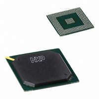
PNX1500E/G,557 NXP Semiconductors, PNX1500E/G,557 Datasheet - Page 548

PNX1500E/G,557
Manufacturer Part Number
PNX1500E/G,557
Description
IC MEDIA PROC 240MHZ 456-BGA
Manufacturer
NXP Semiconductors
Specifications of PNX1500E/G,557
Applications
Multimedia
Core Processor
TriMedia
Controller Series
Nexperia
Interface
I²C, 2-Wire Serial
Number Of I /o
61
Voltage - Supply
1.14 V ~ 1.26 V
Operating Temperature
0°C ~ 85°C
Mounting Type
Surface Mount
Package / Case
456-BGA
Lead Free Status / RoHS Status
Lead free / RoHS Compliant
Program Memory Type
-
Ram Size
-
Lead Free Status / Rohs Status
Compliant
Other names
568-1296
935277746557
PNX1500E/G
935277746557
PNX1500E/G
- Current page: 548 of 828
- Download datasheet (8Mb)
Philips Semiconductors
Volume 1 of 1
PNX15XX_SER_3
Product data sheet
3.2 Register Programming Guidelines
Before enabling the SPDO block, software must assign two buffers with data to
SPDO_BASE1, SPDO_BASE2 and a buffer size value (in bytes) to SPDO_SIZE.
Each memory buffer size must be a multiple of 64 bytes, regardless of the operating
mode.
The SPDO block is enabled by writing a ‘1’ to SPDO_CTL.TRANS_ENABLE. Once
enabled, the first DMA buffer is sent out at the programmed sample rate. Once the
first buffer is empty, BUF1_ACTIVE is negated and the BUF1_EMPTY flag in
SPDO_STATUS is asserted. If BUF1_INTEN in SPDO_CTL is asserted, an interrupt
to the chip level interrupt controller is generated.
The SPDO block continues by emitting the data in DMA buffer2. In normal operation,
software assigns a new buffer 1 full of data to SPDO and signals this by writing a ‘1’ to
ACK_BUF1. The SPDO block immediately negates the BUF1_EMPTY condition and
the related interrupt request. Once buffer2 is empty, similar signalling occurs and the
hardware switches back using buffer1. Transmission continues interrupted until the
unit is disabled.
The SPDO module has two operating modes: SPDIF and transparent DMA mode.
IEC Mode
SPDIF driver software assembles SPDIF data in each memory data buffer. Each
memory data buffer consists of groups of 32 bit words in memory. Each word
describes the data to be transmitted for a single IEC-60958 sub-frame, including what
type of preamble to include. Each sub-frame is transmitted in 64 clock intervals of the
SPDO clock.
The SPDIF mode is also useful for providing a source input stream for an available
SPDIF IN block.
Transparent DMA Mode
In transparent DMA mode, software prepares each data bit exactly as it is to be
transmitted, in a series of 32 bit words in each memory data buffer. The 32 bit word is
constructed according to the byte ordering rules of little or big-endian mode. Each 32-
bit word is transmitted (LSB or MSB first) into 32 clock intervals of the DDS. The data
is shifted out “as is,” without bi-phase mark encoding, parity generation or preamble
insertion.
Rev. 3 — 17 March 2006
© Koninklijke Philips Electronics N.V. 2006. All rights reserved.
Chapter 17: SPDIF Output
PNX15xx Series
17-3
Related parts for PNX1500E/G,557
Image
Part Number
Description
Manufacturer
Datasheet
Request
R

Part Number:
Description:
Manufacturer:
NXP Semiconductors
Datasheet:
Part Number:
Description:
Digital Signal Processors & Controllers - DSP, DSC NEXPERIA MEDIA PROC 240MHZ
Manufacturer:
NXP Semiconductors
Part Number:
Description:
Digital Signal Processors & Controllers - DSP, DSC PNX1500, 240MHZ
Manufacturer:
NXP Semiconductors
Part Number:
Description:
NXP Semiconductors designed the LPC2420/2460 microcontroller around a 16-bit/32-bitARM7TDMI-S CPU core with real-time debug interfaces that include both JTAG andembedded trace
Manufacturer:
NXP Semiconductors
Datasheet:

Part Number:
Description:
NXP Semiconductors designed the LPC2458 microcontroller around a 16-bit/32-bitARM7TDMI-S CPU core with real-time debug interfaces that include both JTAG andembedded trace
Manufacturer:
NXP Semiconductors
Datasheet:
Part Number:
Description:
NXP Semiconductors designed the LPC2468 microcontroller around a 16-bit/32-bitARM7TDMI-S CPU core with real-time debug interfaces that include both JTAG andembedded trace
Manufacturer:
NXP Semiconductors
Datasheet:
Part Number:
Description:
NXP Semiconductors designed the LPC2470 microcontroller, powered by theARM7TDMI-S core, to be a highly integrated microcontroller for a wide range ofapplications that require advanced communications and high quality graphic displays
Manufacturer:
NXP Semiconductors
Datasheet:
Part Number:
Description:
NXP Semiconductors designed the LPC2478 microcontroller, powered by theARM7TDMI-S core, to be a highly integrated microcontroller for a wide range ofapplications that require advanced communications and high quality graphic displays
Manufacturer:
NXP Semiconductors
Datasheet:
Part Number:
Description:
The Philips Semiconductors XA (eXtended Architecture) family of 16-bit single-chip microcontrollers is powerful enough to easily handle the requirements of high performance embedded applications, yet inexpensive enough to compete in the market for hi
Manufacturer:
NXP Semiconductors
Datasheet:
Part Number:
Description:
The XA-S3 device is a member of Philips Semiconductors? XA(eXtended Architecture) family of high performance 16-bitsingle-chip microcontrollers
Manufacturer:
NXP Semiconductors
Datasheet:

Part Number:
Description:
The NXP BlueStreak LH75401/LH75411 family consists of two low-cost 16/32-bit System-on-Chip (SoC) devices
Manufacturer:
NXP Semiconductors
Datasheet:

Part Number:
Description:
The NXP LPC3130/3131 combine an 180 MHz ARM926EJ-S CPU core, high-speed USB2
Manufacturer:
NXP Semiconductors
Datasheet:

Part Number:
Description:
The NXP LPC3141 combine a 270 MHz ARM926EJ-S CPU core, High-speed USB 2
Manufacturer:
NXP Semiconductors

Part Number:
Description:
The NXP LPC3143 combine a 270 MHz ARM926EJ-S CPU core, High-speed USB 2
Manufacturer:
NXP Semiconductors


