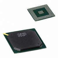
PNX1500E/G,557 NXP Semiconductors, PNX1500E/G,557 Datasheet - Page 786

PNX1500E/G,557
Manufacturer Part Number
PNX1500E/G,557
Description
IC MEDIA PROC 240MHZ 456-BGA
Manufacturer
NXP Semiconductors
Specifications of PNX1500E/G,557
Applications
Multimedia
Core Processor
TriMedia
Controller Series
Nexperia
Interface
I²C, 2-Wire Serial
Number Of I /o
61
Voltage - Supply
1.14 V ~ 1.26 V
Operating Temperature
0°C ~ 85°C
Mounting Type
Surface Mount
Package / Case
456-BGA
Lead Free Status / RoHS Status
Lead free / RoHS Compliant
Program Memory Type
-
Ram Size
-
Lead Free Status / Rohs Status
Compliant
Other names
568-1296
935277746557
PNX1500E/G
935277746557
PNX1500E/G
- Current page: 786 of 828
- Download datasheet (8Mb)
Philips Semiconductors
Volume 1 of 1
PNX15XX_SER_3
Product data sheet
1.1.3 Peripheral Module Wakeup Sequence
1.1.4 TM3260 Powerdown Modes
Remark: This bit does NOT gate the internal module clock or other clocks as clock
gating is not allowed inside a module.
Waking up a module is also under CPU control and is the reverse sequence to
powerdown:
The TM3260 CPU has two modes: Partial Powerdown and Full Powerdown.
Partial Powerdown Mode
The TM3260 CPU enters partial powerdown mode by performing a 'store' to a
specific MMIO address (the POWERDOWN register). The TM3260 then finishes any
pending transactions and go into a partial powerdown. In partial powerdown mode,
cycle counters, timers and interrupt logic in the TM3260 are still active. The TM3260
CPU wakes up from partial powerdown when an interrupt occurs or there is an
access to its MMIO space. This commonly used by the idle task in an operating
system.
Full Powerdown Mode
The TM3260 also have an externally-initiated full power shutdown mode i.e., no
wakeups when an interrupt occurs. Entering this mode is requested by asserting an
input signal to the TM3260. When this signal is asserted, the TM3260 finishes
pending transactions and gates-off its core clock.
•
•
•
•
•
•
•
•
The CPU writes/sets the device's POWERDOWN control bit (usually bit 31 of
offset 0xFF4). Setting this bit causes the device to power down elements such as
memories and register files.
After setting the powerdown bit, none of the device's registers is accessible,
except the one containing the POWERDOWN bit, which is 100% operational.
–
–
The CPU programs the Clock module to stop/slow down the clock signals. This
assures the Clock module is stopped in a controlled way (no glitches/illegal
periods).
At this point, the register with the POWERDOWN bit is still the only accessible
register and the block is fully powered down.
Program the Clock module so that all related clock sources are set to their normal
operational frequencies.
Reset the POWERDOWN bit in the module.
Set up the module's configuration registers if needed.
Enable the module.
Reads from any other register do not hang.
Writes to any register (except the POWERDOWN bit register) are completed
fully or result in an error.
Rev. 3 — 17 March 2006
Chapter 27: Power Management
© Koninklijke Philips Electronics N.V. 2006. All rights reserved.
PNX15xx Series
27-2
Related parts for PNX1500E/G,557
Image
Part Number
Description
Manufacturer
Datasheet
Request
R

Part Number:
Description:
Manufacturer:
NXP Semiconductors
Datasheet:
Part Number:
Description:
Digital Signal Processors & Controllers - DSP, DSC NEXPERIA MEDIA PROC 240MHZ
Manufacturer:
NXP Semiconductors
Part Number:
Description:
Digital Signal Processors & Controllers - DSP, DSC PNX1500, 240MHZ
Manufacturer:
NXP Semiconductors
Part Number:
Description:
NXP Semiconductors designed the LPC2420/2460 microcontroller around a 16-bit/32-bitARM7TDMI-S CPU core with real-time debug interfaces that include both JTAG andembedded trace
Manufacturer:
NXP Semiconductors
Datasheet:

Part Number:
Description:
NXP Semiconductors designed the LPC2458 microcontroller around a 16-bit/32-bitARM7TDMI-S CPU core with real-time debug interfaces that include both JTAG andembedded trace
Manufacturer:
NXP Semiconductors
Datasheet:
Part Number:
Description:
NXP Semiconductors designed the LPC2468 microcontroller around a 16-bit/32-bitARM7TDMI-S CPU core with real-time debug interfaces that include both JTAG andembedded trace
Manufacturer:
NXP Semiconductors
Datasheet:
Part Number:
Description:
NXP Semiconductors designed the LPC2470 microcontroller, powered by theARM7TDMI-S core, to be a highly integrated microcontroller for a wide range ofapplications that require advanced communications and high quality graphic displays
Manufacturer:
NXP Semiconductors
Datasheet:
Part Number:
Description:
NXP Semiconductors designed the LPC2478 microcontroller, powered by theARM7TDMI-S core, to be a highly integrated microcontroller for a wide range ofapplications that require advanced communications and high quality graphic displays
Manufacturer:
NXP Semiconductors
Datasheet:
Part Number:
Description:
The Philips Semiconductors XA (eXtended Architecture) family of 16-bit single-chip microcontrollers is powerful enough to easily handle the requirements of high performance embedded applications, yet inexpensive enough to compete in the market for hi
Manufacturer:
NXP Semiconductors
Datasheet:
Part Number:
Description:
The XA-S3 device is a member of Philips Semiconductors? XA(eXtended Architecture) family of high performance 16-bitsingle-chip microcontrollers
Manufacturer:
NXP Semiconductors
Datasheet:

Part Number:
Description:
The NXP BlueStreak LH75401/LH75411 family consists of two low-cost 16/32-bit System-on-Chip (SoC) devices
Manufacturer:
NXP Semiconductors
Datasheet:

Part Number:
Description:
The NXP LPC3130/3131 combine an 180 MHz ARM926EJ-S CPU core, high-speed USB2
Manufacturer:
NXP Semiconductors
Datasheet:

Part Number:
Description:
The NXP LPC3141 combine a 270 MHz ARM926EJ-S CPU core, High-speed USB 2
Manufacturer:
NXP Semiconductors

Part Number:
Description:
The NXP LPC3143 combine a 270 MHz ARM926EJ-S CPU core, High-speed USB 2
Manufacturer:
NXP Semiconductors


