Z8018010PSG Zilog, Z8018010PSG Datasheet - Page 111
Z8018010PSG
Manufacturer Part Number
Z8018010PSG
Description
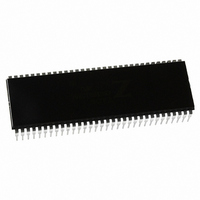
IC 10MHZ Z180 CMOS ENH MPU 64DIP
Manufacturer
Zilog
Specifications of Z8018010PSG
Processor Type
Z180
Features
8-Bit, Enhanced Z80 Megacell
Speed
10MHz
Voltage
5V
Mounting Type
Through Hole
Package / Case
64-DIP (0.750", 19.05mm)
Processor Series
Z8018xx
Core
Z80
Data Bus Width
8 bit
Maximum Clock Frequency
10 MHz
Number Of Timers
2
Operating Supply Voltage
0 V to 5 V
Maximum Operating Temperature
+ 70 C
Mounting Style
Through Hole
Minimum Operating Temperature
0 C
Core Size
8bit
Cpu Speed
10MHz
Digital Ic Case Style
DIP
No. Of Pins
64
Supply Voltage Range
4.5V To 5.5V
Operating Temperature Range
0°C To +70°C
Svhc
No SVHC (18-Jun-2010)
Base Number
8018010
Rohs Compliant
Yes
Clock Frequency
10MHz
Lead Free Status / RoHS Status
Lead free / RoHS Compliant
Other names
269-3889
Z8018010PSG
Z8018010PSG
Available stocks
Company
Part Number
Manufacturer
Quantity
Price
Company:

Part Number:
Z8018010PSG
Manufacturer:
Zilog
Quantity:
40


96
UM005003-0703
Bit
Position Bit/Field R/W
6
5
4
3
2
Z8018x
Family MPU User Manual
DE0
DWE1
DWE0
DIE1
DIE0
R/W
W
W
R/W
Value
Description
Enable Channel 0 — When DE0 = 1 and DME = 1,
channel 0 DMA is enabled. When a DMA transfer
terminates BCR0 = 0), DE0: is reset to 0 by the DMAC.
When DE0 = 0 and the DMA interrupt is enabled (DIE0 =
1), a DMA interrupt request is made to the CPU.
To perform a software write to DE0, DWE0 must be written
with 0 during the same register write access. Writing DE0 to
0 disables channel 0 DMA. Writing DE0 to 1 enables
channel 0 DMA and automatically sets DME (DMA Main
Enable) to 1. DE0 is cleared to 0 during RESET.
Bit Write Enable 1 — When performing any software
write to DEI, DWE1 must be written with 0 during the
same access. DWE1 write value of 0 is not held and
DWE1 is always read as 1.
Bit Write Enable 0 — When performing any software
write to DE0, DWE0 must be written with 0 during the
same access. DWE0 write value of 0 is not held and
DWE0 is always read as 1.
DMA Interrupt Enable Channel 1 — When DIE1 is set
to 1, the termination channel 1 DMA transfer (indicated
when DE1 is 0) causes a CPU interrupt request to be
generated. When DIE1 is 0, the channel 1 DMA
termination interrupt is disabled. DIE1 is cleared to 0
during RESET.
DMA Interrupt Enable Channel 0 — When DIE0 is set
to 1, the termination channel 0 of DMA transfer
(indicated when DE0 is 0) causes a CPU interrupt request
to be generated. When DIE0 is 0, the channel 0 DMA
termination interrupt is disabled. DIE0 is cleared to 0
during RESET.
Related parts for Z8018010PSG
Image
Part Number
Description
Manufacturer
Datasheet
Request
R

Part Number:
Description:
Microprocessor Unit
Manufacturer:
ZiLOG Semiconductor
Datasheet:

Part Number:
Description:
Z80180 EMULATOR
Manufacturer:
Zilog
Datasheet:
Part Number:
Description:
Z80180, Z8s180, Z8l180 Mpu Operation
Manufacturer:
ZiLOG Semiconductor
Datasheet:

Part Number:
Description:
Communication Controllers, ZILOG INTELLIGENT PERIPHERAL CONTROLLER (ZIP)
Manufacturer:
Zilog, Inc.
Datasheet:

Part Number:
Description:
KIT DEV FOR Z8 ENCORE 16K TO 64K
Manufacturer:
Zilog
Datasheet:

Part Number:
Description:
KIT DEV Z8 ENCORE XP 28-PIN
Manufacturer:
Zilog
Datasheet:

Part Number:
Description:
DEV KIT FOR Z8 ENCORE 8K/4K
Manufacturer:
Zilog
Datasheet:

Part Number:
Description:
KIT DEV Z8 ENCORE XP 28-PIN
Manufacturer:
Zilog
Datasheet:
Part Number:
Description:
DEV KIT FOR Z8 ENCORE 4K TO 8K
Manufacturer:
Zilog
Datasheet:
Part Number:
Description:
CMOS Z8 microcontroller. ROM 16 Kbytes, RAM 256 bytes, speed 16 MHz, 32 lines I/O, 3.0V to 5.5V
Manufacturer:
Zilog, Inc.
Datasheet:
Part Number:
Description:
Low-cost microcontroller. 512 bytes ROM, 61 bytes RAM, 8 MHz
Manufacturer:
Zilog, Inc.
Datasheet:
Part Number:
Description:
Z8 4K OTP Microcontroller
Manufacturer:
Zilog, Inc.
Datasheet:
Part Number:
Description:
CMOS SUPER8 ROMLESS MCU
Manufacturer:
Zilog, Inc.
Datasheet:
Part Number:
Description:
SL1866 CMOSZ8 OTP Microcontroller
Manufacturer:
Zilog, Inc.
Datasheet: